

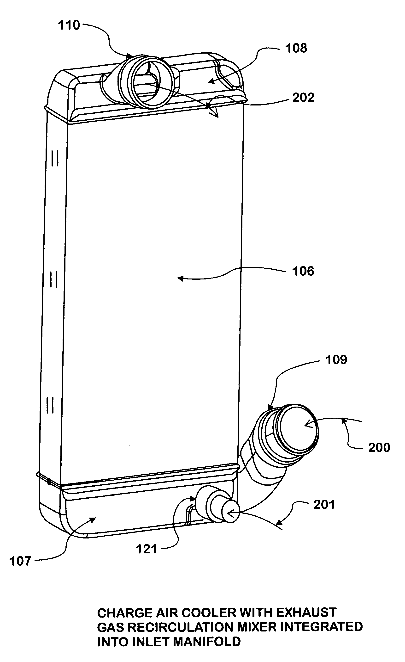
Integrated charge air cooler and exhaust gas recirculation mixer
a technology of exhaust gas recirculation mixer and charge air cooler, which is applied in the direction of combustion air/fuel air treatment, machines/engines, mechanical equipment, etc., can solve the problems of increasing the intake system of the internal combustion reciprocating engine to an increased number of potential leakage points, requiring additional installation, and reducing the overall cost of the vehicle. , the effect of reducing the overall cost of the vehicl
- Summary
- Abstract
- Description
- Claims
- Application Information
AI Technical Summary
Benefits of technology
Problems solved by technology
Method used
Image

Examples
Embodiment Construction
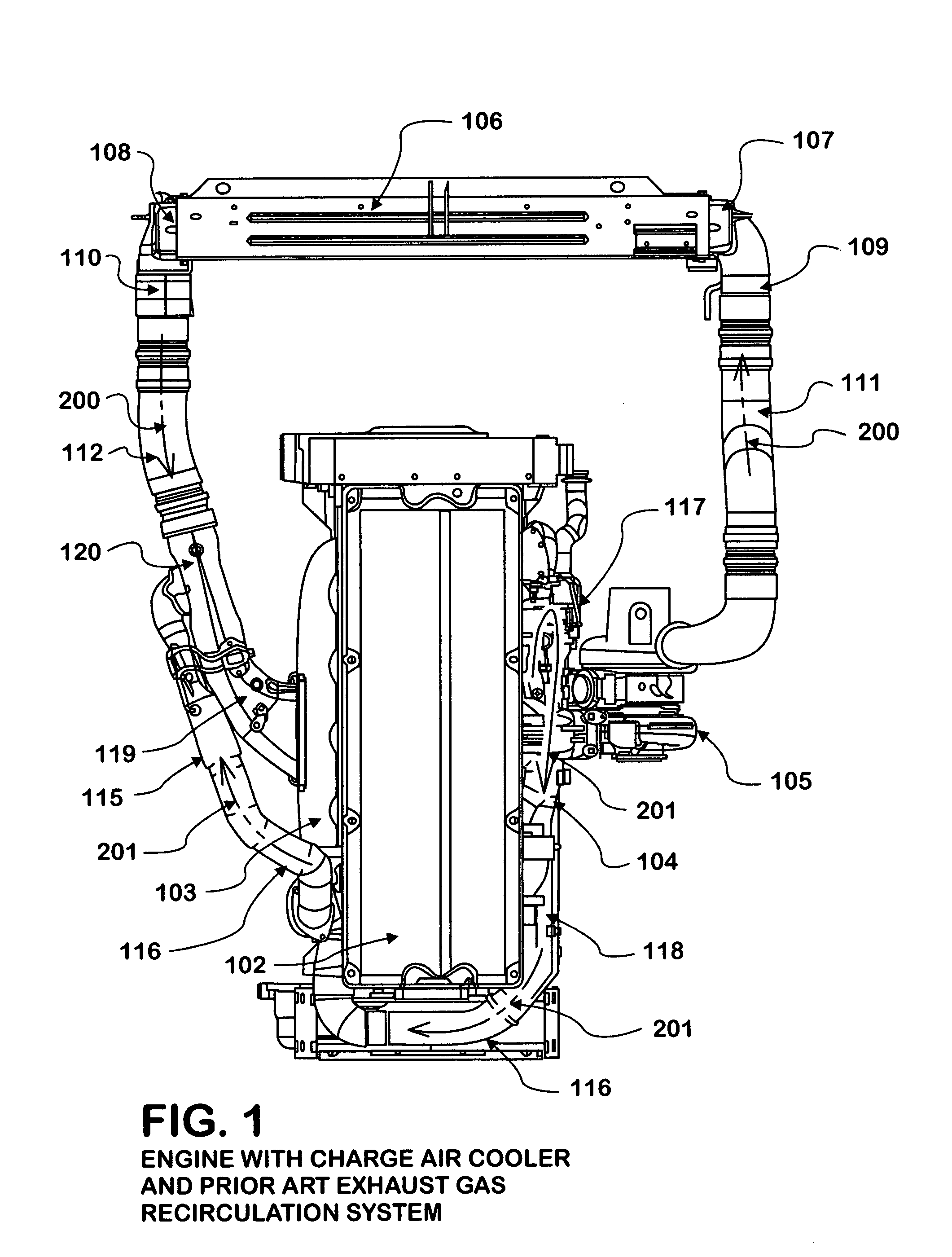
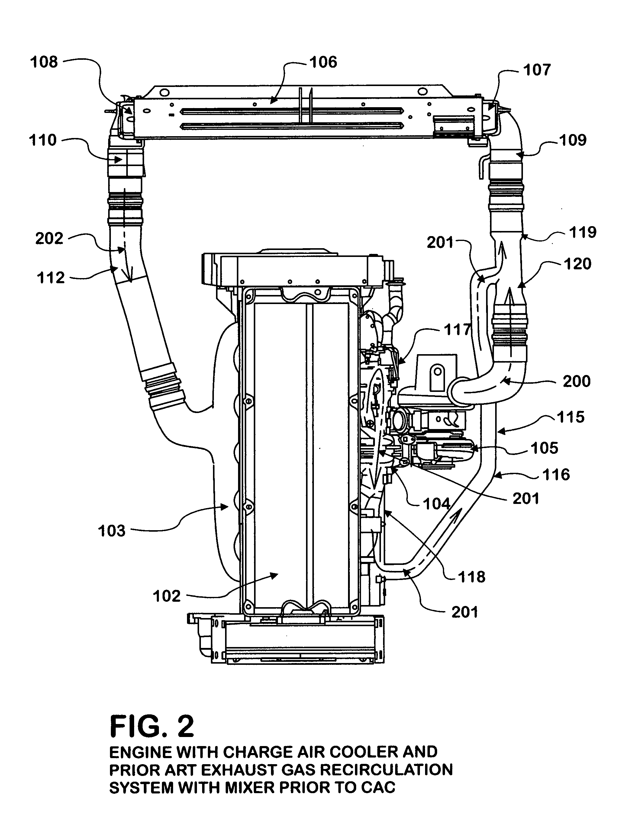
[0029]FIG. 1 shows an engine 102 having a charge air cooler 106 and a prior art exhaust gas recirculation system 115. The engine 102 is provided with an engine intake manifold 103 and an engine exhaust manifold 104, to which engine exhaust manifold 104 is attached a turbocharger 105. The turbocharger 105 functions to extract mechanical energy from the exhaust 201 produced by the engine 102, and utilize the mechanical energy to compress the intake air 200, which intake air 200 is conveyed to the charge air cooler 106 by the turbo to charge air cooler pipe 111. The intake air 200 enters the charge air cooler 106 at the charge air cooler inlet 109, and is distributed evenly across the charge air cooler 106 by use of a charge air cooler inlet manifold 107. As the intake air 200 exits the charge air cooler 106, it is collected in the charge air cooler outlet manifold 108, before exiting through the charge air cooler outlet 110. The intake air 200 is then conveyed to an exhaust gas recirc...
PUM
 Abstract
Description
Claims
Application Information