
Forming fabric with extended surface

Inactive Publication Date: 2008-01-31
VOITH PATENT GMBH
View PDF11 Cites 27 Cited by
  • Summary
  • Abstract
  • Description
  • Claims
  • Application Information

AI Technical Summary

Benefits of technology

[0015]Additionally, the present invention is for a forming fabric that produces a structured sheet in the Advanced Dewatering System (ADS, also known as Advanced Tissue Molding System, or ATMOS) machine, which produces the same quality, bulk and water absorbency as TAD machines and do the micro-embossing with the molding fabric and the macro-embossing with the special developed forming fabric. Since the produced sheet is already wet structured in the machine, there is no need to further emboss the sheet going through an expensive converting line to press the micro and macro structures into the sheet. By pressing the structure into the dry sheet, on a converting line, the sheet is compacted, thus the quality, bulk, volume and absorbency capacity are reduced. In ATMOS, the speed of the paper stays approximately the same during fabric transfer.
[0019]Accordingly, a structured sheet like a TAD product is produced, with the same premium quality, but without using the extensive TAD machine. There is 40% less capital investment, less machine equipment, less civil work, simplified building, easier operation, less maintenance and 35% less total consumable cost (energy, clothing, chemicals).
[0020]Another big advantage of this solution is that the sheet is formed over a structured fabric, starting with very low consistency, between about 0.15 to 0.35% and the same structured fabric is carrying the fibers protected within its structure from the headbox to the transfer to the Yankee dryer. Against the Yankee dryer, only the fibers at the knuckle area of the molding fabric will be pressed, and the protected fibers, within the body of the structured fabric, remain unpressed for quality. The objective is to fill the valleys of the structured fabric with the maximum amount of fibers, because this will be the mass of unpressed fibers which will give the final premium paper quality.
[0021]Since the produced sheet is already structured, there is no need to further emboss the sheet going through an expensive converting line to press the micro and macro structures into the sheet. By pressing the structure into the dry sheet, in a converting line, the sheet is compacted, thus the quality, bulk, volume and absorbency capacity is reduced.

Problems solved by technology

Varying amounts of water is removed from the slurry through the forming fabric, resulting in the formation of a fibrous web on the surface of the forming fabric.
Additionally, if drainage of water from the slurry occurs to rapidly or too slowly, the quality of the fibrous web is reduced, and overall machine production efficiency is reduced.
This results in a weakness of the fibrous web in the areas of lower fiber concentration.
While printed forming fabrics can be used on conventional tissue machines, there is no advantage by using them on conventional tissue machines, were the sheet is 100% pressed and the bulk is too low to produce micro-embossed and macro-embossed sheet in the machine and a converting line to emboss the sheet is needed.

Method used


Image

  • Forming fabric with extended surface
  • Forming fabric with extended surface
  • Forming fabric with extended surface

Examples


Embodiment Construction

[0039]The particulars shown herein are by way of example and for purposes of illustrative discussion of the embodiments of the present invention only and are presented in the cause of providing what is believed to be the most useful and readily understood description of the principles and conceptual aspects of the present invention. In this regard, no attempt is made to show structural details of the present invention in more detail than is necessary for the fundamental understanding of the present invention, the description taken with the drawings making apparent to those skilled in the art how the several forms of the present invention may be embodied in practice.

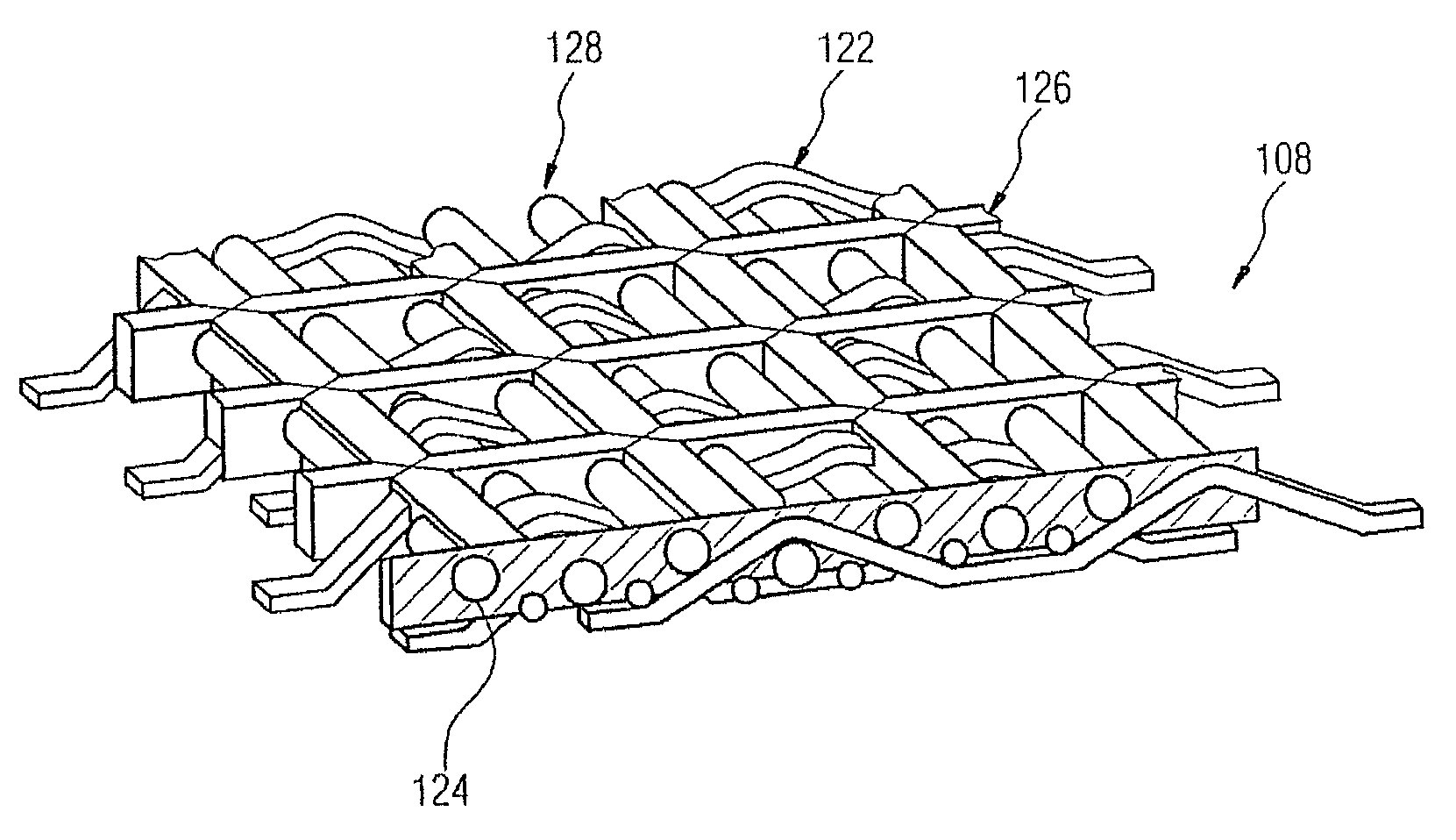
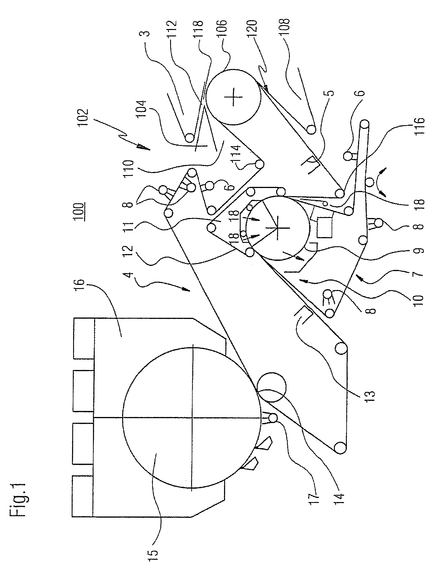
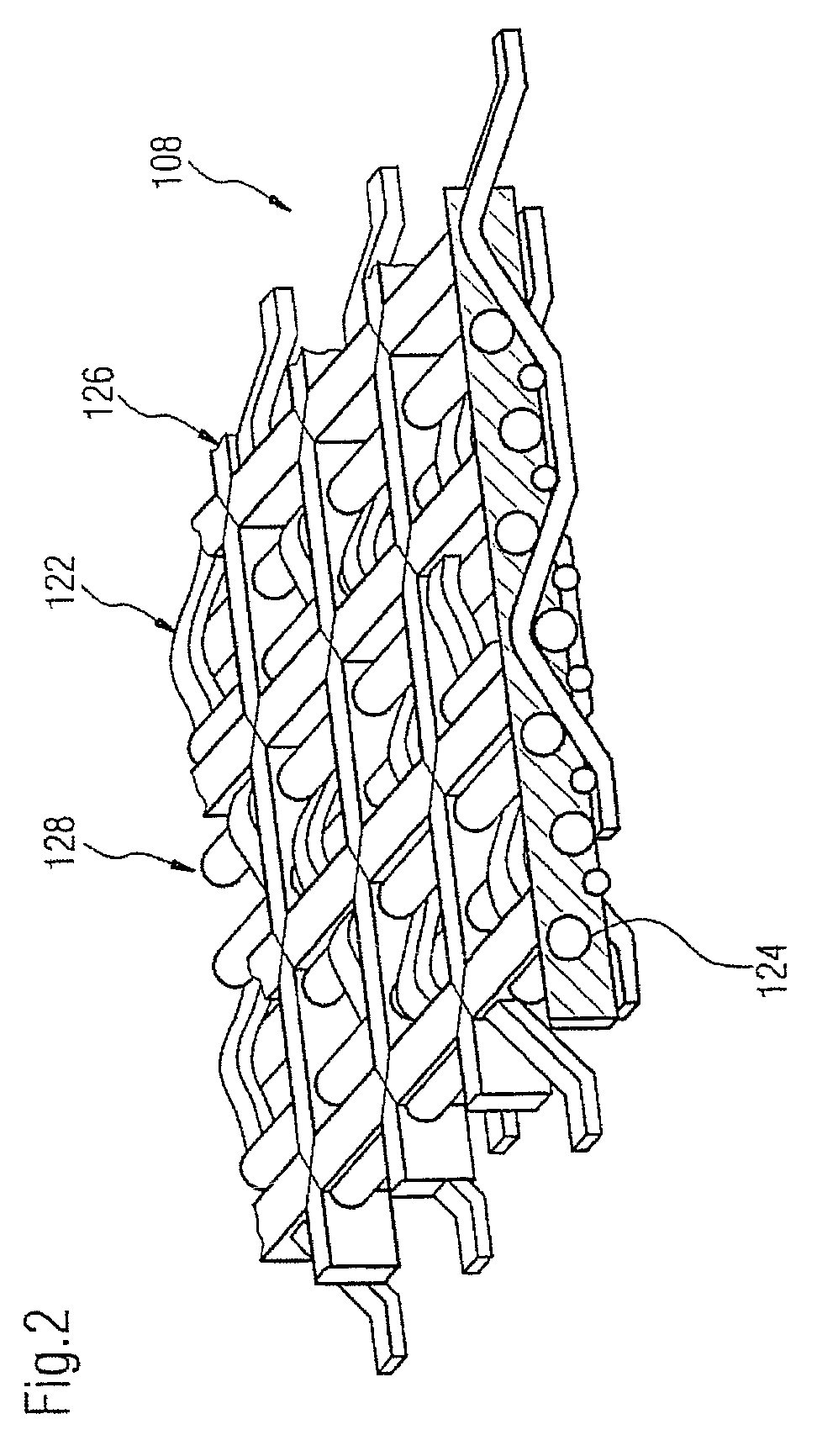
[0040]FIG. 1 is a schematic of an advanced dewatering system 100. The forming area 102 is in the initial dewatering area having a head box 104, a forming roll 106, a forming fabric 108 and a molding fabric 110. More specifically, the forming roll 106 has two continuous rotating dewatering belts 108, 110 that converge, for...


PUM

PropertyMeasurementUnit
Fractionaaaaaaaaaa
Fractionaaaaaaaaaa
Fractionaaaaaaaaaa

Abstract

A fabric for an advanced dewatering system having a woven fabric, the woven fabric having a paper side and a roll side. The paper side has a paper side surface and the roll side has a roll side surface; and a polymer material is deposited onto the fabric that extends above the paper side surface. The polymer material has at least one of a random pattern, a random motif, a pseudo-random pattern, a pseudo-random motif, a predetermined pattern, and a predetermined motif.

Description

CROSS-REFERENCE TO RELATED APPLICATIONS[0001]Not Applicable.STATEMENT REGARDING FEDERALLY SPONSORED RESEARCH OR DEVELOPMENT[0002]Not applicable.REFERENCE TO A COMPACT DISK APPENDIX[0003]Not applicable.BACKGROUND OF THE INVENTION[0004]1. Field of the Invention[0005]The invention relates to a fabric used in papermaking. More specifically, the present invention relates to forming fabrics used in the forming section of a papermaking machine, and more specifically, to a forming fabric for use in tissue making.[0006]2. Description of Background[0007]In the art of papermaking, multiple steps occur from the introduction of a pulp slurry to the output of a finished paper product. The initial introduction of the slurry is at the portion of a papermaking machine known as the wet end. Here, the slurry, or fiber suspension, is initially dewatered when the slurry is introduced onto a moving forming fabric, in the forming section of the papermaking machine. Varying amounts of water is removed from...

Claims


Application Information

Patent Timeline
IPC IPC(8): D21F3/00B32B5/02
CPCD21F1/0027D21F11/145D21F11/14D21F11/006Y10T442/20Y10T442/172
Inventor FERNANDES, LIPPI A.RINGER, MARTINMORTON, ANTHONYJEFFERY, JOHNPAYNE, JUSTIN
Owner VOITH PATENT GMBH
Features
  • Generate Ideas
  • Intellectual Property
  • Life Sciences
  • Materials
  • Tech Scout
  • Unparalleled Data Quality
  • Higher Quality Content
  • 60% Fewer Hallucinations
Learn More