Method for manufacturing piezoelectric resonator

a manufacturing method and piezoelectric technology, applied in piezoelectric/electrostrictive transducers, device material selection, transducer types, etc., can solve the problems of increasing the number of total processes, reducing the yield, and increasing the cost, so as to reduce the amount of metal, prevent the yield from being reduced, and widen the frequency adjustment margin

Inactive Publication Date: 2008-01-31
NIHON DEMPA KOGYO CO LTD
View PDF2 Cites 7 Cited by
  • Summary
  • Abstract
  • Description
  • Claims
  • Application Information

AI Technical Summary

Benefits of technology

[0043]According to the present invention, the metal film used at the time of forming the outside shape portion and the groove of the piezoelectric oscillating piece is preserved at the tip of the vibrating arm and thereafter, a metal film to be an electrode is newly formed on the surface of the substrate. Accordingly, the film thickness of the metal film formed at the tip of the oscillating is increased, and as a result, a margin of the frequency adjustment is widened. As a result, it is possible to prevent the yield from reduction and to reduce the amount of metal which will be used to form an electrode in the next electrode pattern formation process. Therefore, especially when gold (Au) is used as the metal, the effect of saving metal is great because gold is very expensive.

Problems solved by technology

There are however the following disadvantages in the process of adjusting the oscillation frequency.
Therefore, when the metal film 14 is used as it is for an adjustment film to adjust the oscillation frequency, it has the disadvantage of reduction in yield due to extreme narrowness of the allowable adjustment range in frequency.
However, it needs increased amount of metal to be used, and especially when gold (Au) is used as the metal, it has the disadvantage of increase in cost.
This requires a new specific process for forming a metal film for frequency adjustment, after forming the aperture on the resist mask, which result in an increase in the number of the total processes, and thus bringing a disadvantage of making the manufacturing process intricate.

Method used


Image

  • Method for manufacturing piezoelectric resonator
  • Method for manufacturing piezoelectric resonator
  • Method for manufacturing piezoelectric resonator

Examples


embodiment

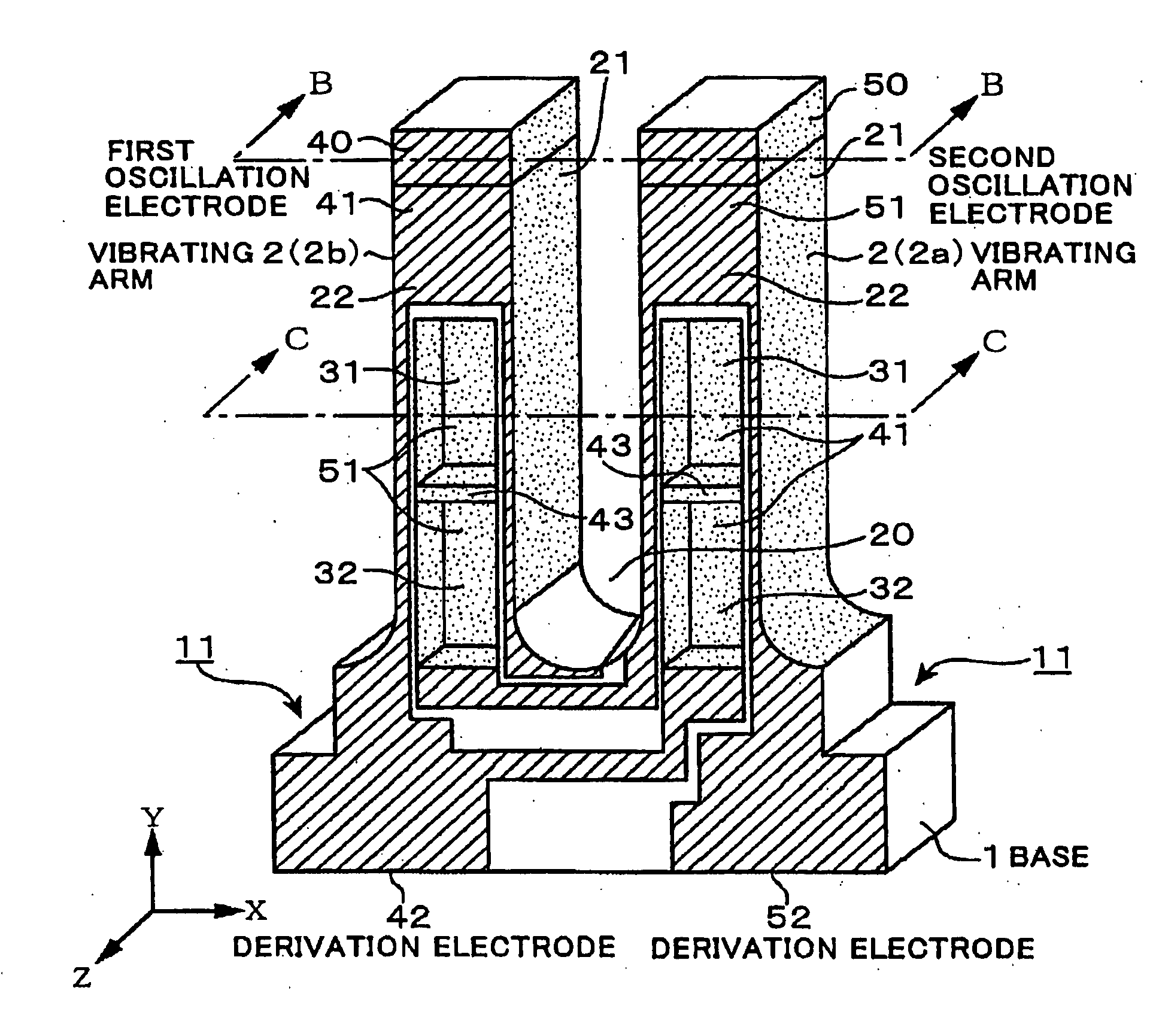
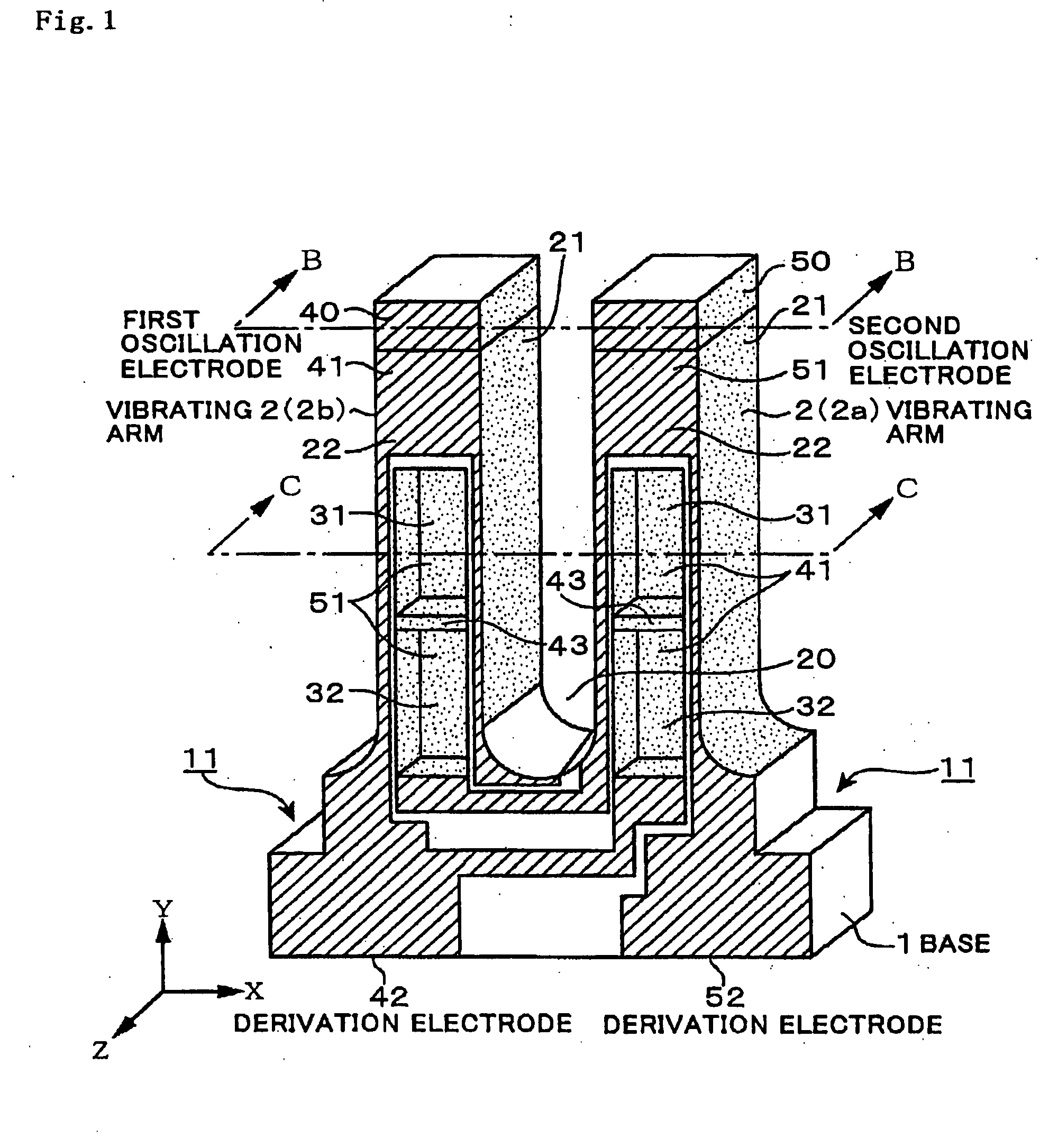
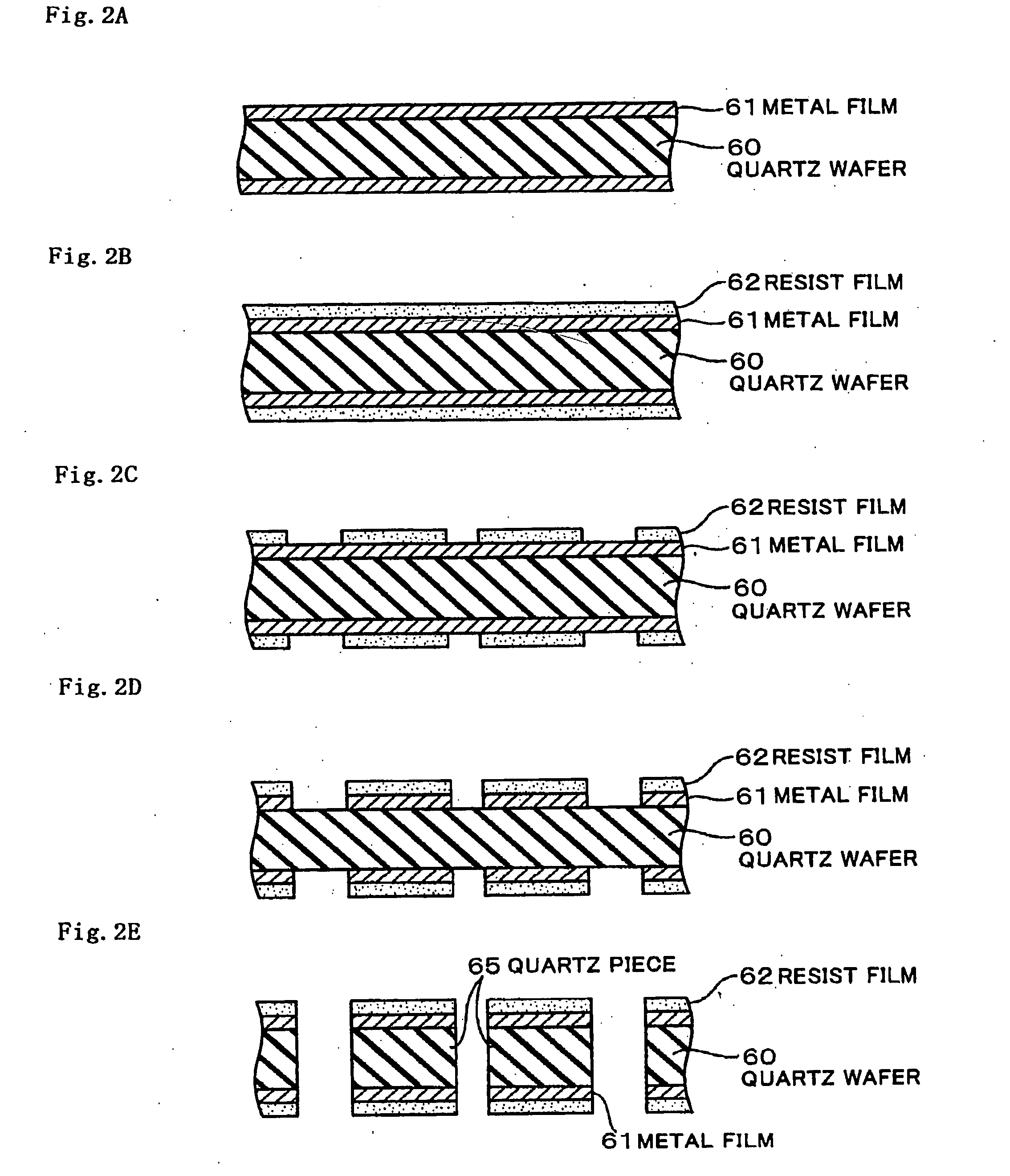
[0073]In a case of manufacturing a quartz resonator of 32 kHz, the change of frequency caused by shaving all of the surfaces of the metal films 61 and 67, which are formed at the tips of the vibrating arms 2a and 2b of the quartz resonator of the present invention manufactured by the processes shown in FIG. 2A to FIG. 6S is found to be about 15,000 ppm. The film thickness of the metal films 61 and 67 is 0.4 μm. This is the embodiment.

[0074]The change of frequency caused by shaving all of the surfaces of the metal film 14, which is formed at the tips of the vibrating arms 2a and 2b of a conventional quartz resonator manufactured by the processes shown in FIG. 10A to FIG. 12N is found to be about 4,000 ppm. The film thickness of the metal film 14 is 0.1 μm. This is taken as a comparison example.

[0075]Therefore, while the amount of frequency adjustment in the comparison example is 4,000 ppm, that in the embodiment is about four times greater of 15,000 ppm. This makes it possible to imp...


PUM

PropertyMeasurementUnit
thicknessaaaaaaaaaa
thicknessaaaaaaaaaa
thicknessaaaaaaaaaa

Abstract

To provide a method for manufacturing a piezoelectric resonator which can widen the range of frequency adjustment while saving metal thereby suppressing reduction of the yields when forming a metal film for frequency adjustment at the tip of an vibrating arm. The method of manufacturing the piezoelectric resonator according to the present invention includes the steps of: bringing a substrate in which an outside shape of a piezoelectric oscillating piece is formed, into contact with an etching solution; forming grooves in a plurality of vibrating arms using a mask having an aperture at the portion corresponding to the groove, and having a metal film formed on the whole surface except the aperture; and thereafter, forming a resist mask on the surface of the substrate so that resist is left at the tip of the vibrating arms which will be a formation area of a metal film for frequency adjustment so as to remove the metal film by etching. Then, forming an electrode film after peeling off the resist film left at the tip of the vibrating arm.

Description

BACKGROUND OF THE INVENTION[0001]1. Field of the Invention[0002]The present invention relates to a technology for manufacturing, for instance, a tuning fork type piezoelectric resonator using a piezoelectric substrate made of, for instance, quartz crystal or the like.[0003]2. Description of the Related Art[0004]The tuning fork type quartz resonator has long been adopted as a signal source for pacing of a wrist watch owing to its compactness, inexpensiveness and low power consumption, and the uses thereof are still expanding. The CI (crystal impedance) value of this quartz resonator is required to be as small as possible for the purpose of reducing the power loss, and therefore a quartz resonator of which oscillation efficiency is enhanced by forming a groove therein has been used for this purpose.[0005]As shown in FIG. 9, the quartz resonator is provided with a pair of vibrating arms 2a and 2b in a base 1, and the grooves 31 and 32 are respectively arranged on both main surfaces of ...

Claims


Application Information

Patent Timeline
Patent Type & Authority Applications(United States)
IPC IPC(8): H03H9/15H01L41/09H01L41/18H01L41/22H01L41/23H01L41/253H01L41/29H01L41/332H03H3/02H03H3/04H03H9/19
CPCH03H3/02H03H3/04Y10T29/42H03H2003/026H03H9/215
Inventor HIRANO, KEISUKE
Owner NIHON DEMPA KOGYO CO LTD
Why Eureka
Try Eureka