Antenna arrangement

a wireless communication system and antenna technology, applied in the direction of antenna equipment with additional functions, electrical apparatus, solid-state devices, etc., can solve the problem of limiting communication to distances of typically 5 to 20 metres, and achieve the effect of reducing the size of the communication devi

Inactive Publication Date: 2008-01-31
ITI SCOTLAND
View PDF6 Cites 161 Cited by
  • Summary
  • Abstract
  • Description
  • Claims
  • Application Information

AI Technical Summary

Benefits of technology

[0019] By using a combined antenna and beat sink in this way, the invention has the advantage of enabling the size of a communications device to be reduced.

Problems solved by technology

However, this has the limitation of limiting communication to distances of typically 5 to 20 metres.

Method used


Image

  • Antenna arrangement
  • Antenna arrangement
  • Antenna arrangement

Examples


Embodiment Construction

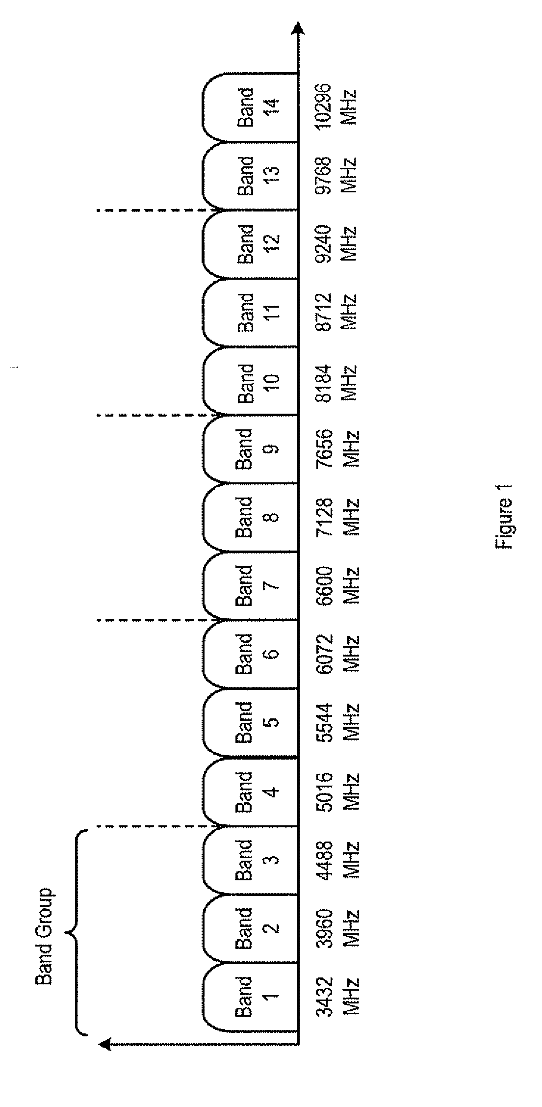
[0030] Although the invention will be described further herein as being adapted for use in an ultra wideband network, it will be appreciated that the invention can be adapted for use in other types of network.

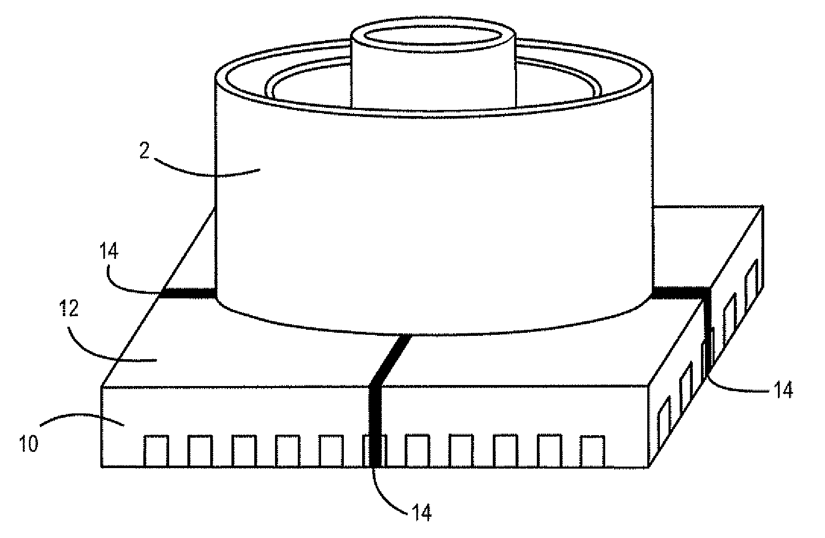
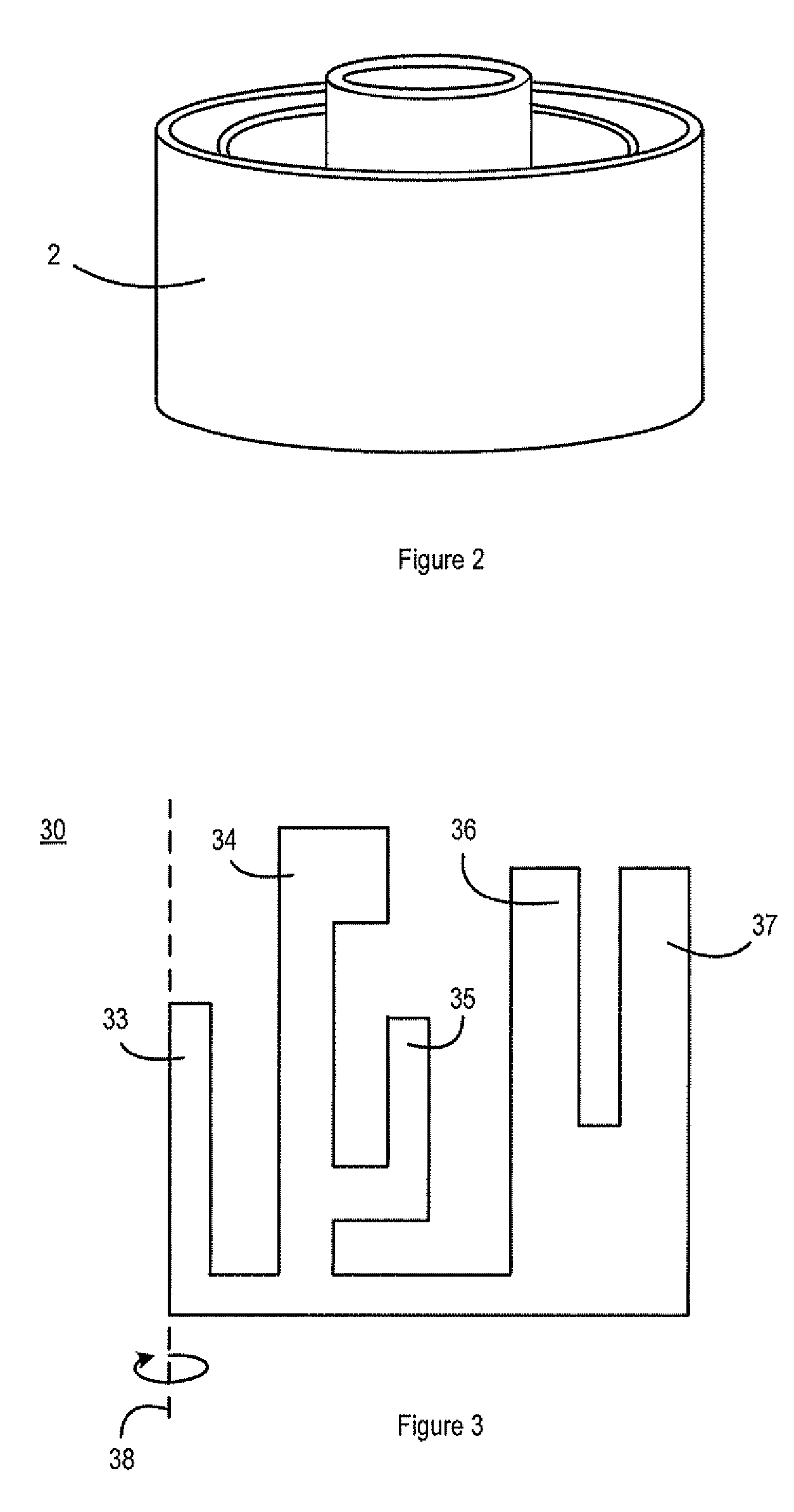
[0031]FIGS. 2 and 3 show an exemplary omni-directional ultra-wideband antenna 2 in accordance with the invention. The antenna 2 is formed as a three-dimensional structure, and is formed as a cast or extruded metal construction. However, it will be appreciated that the antenna 2 can be formed from other suitable material. FIG. 3 shows an antenna element used to form the exemplary antenna 2. Preferably, the antenna element comprises a meander-line structure 30, which includes a plurality of fins 33, 34, 35, 36 and 37. It will be appreciated that other configurations of fins can be used in an antenna in accordance with the invention.

[0032] The three-dimensional antenna 2 may be formed by rotating the meander-line structure 30 shown in FIG. 3 around an axis 38 parallel to the lef...


PUM


Abstract

There is provided an antenna for use in an ultra-wideband device, wherein the antenna is used as an RF radiator and as a heat sink. There is also provided a device for use in an ultra wideband network, the device comprising a component, for example an integrated circuit package, that generates unwanted heat as part of its normal operation, the device further comprising an antenna as described above placed in thermal contact with the component. The antenna may be electrically connected to one or more pins of the component. Alternatively, the antenna may be capacitively connected to the component. There is also provided a heat sink for a wireless communications device, the heat sink being shaped such that it can operate as an antenna for radio frequencies.

Description

BACKGROUND [0001] 1. Field of the Invention [0002] The present invention relates generally to an antenna arrangement for a wireless communication system, and in particular relates to an antenna arrangement for use in an ultra wideband (UWB) wireless communication system. [0003] 2. Background of the Invention [0004] Ultra-wideband is a radio technology that transmits digital data across a very wide frequency range, 3.1 to 10.6 GHz. It makes use of ultra low transmission power, typically less than −41 dBm / MHz, so that the technology can literally hide under other transmission frequencies such as existing Wi-Fi, GSM and Bluetooth. This means that ultra-wideband can co-exist with other radio frequency technologies. However, this has the limitation of limiting communication to distances of typically 5 to 20 metres. [0005] There are two approaches to UWB: the time-domain approach, which constructs a signal from pulse waveforms with UWB properties, and a frequency-domain modulation approac...

Claims


Application Information

Patent Timeline
Patent Type & Authority Applications(United States)
IPC IPC(8): H01Q1/44
CPCH01L23/3672H01Q1/44H01Q23/00H01L2924/0002H01L2924/00H01L23/34
Inventor NORRIS, MARKWILLIAMS, NEILPHILIPPAKIS, MICHAEL
Owner ITI SCOTLAND
Why Eureka
Try Eureka