
Fuel gas generation and supply device

a gas generation and supply device technology, applied in the direction of combustible gas production, electrochemical generators, soldering devices, etc., can solve the problems of reducing the efficiency of catalysts, reducing the rate of fuel gas generating chemical reactions, and reducing the gas generation rate, etc., to achieve safe and convenient use, increase compactness, and small size

Inactive Publication Date: 2008-01-31
NK TECH
View PDF0 Cites 7 Cited by
  • Summary
  • Abstract
  • Description
  • Claims
  • Application Information

AI Technical Summary

Benefits of technology

[0020] A stable supply of fuel gas may be generated and supplied in a constant amount according to the above described first through fifth aspects of the invention. The parameters for producing a fixed chemical reaction rate may be set by at least one of the concentration of oxidation catalyst material dissolved in the liquid, the performance characteristics the solid oxidation catalyst material, the supply rate of the liquid to the permeable member, and the surface area of the permeable member in contact with the liquid solution. In accordance with the concepts and principles of the invention, these features play a part in the provision of a mobile device that is practical with a small, simple structure, that is inexpensive, safe and convenient to use, and that may be constructed using a resin molding or the like. A device constructed using the present concepts, is not limited to chemical reactions using a liquid catalytic solution and a solid component to produce the fuel gas. Rather, in accordance with the invention it is possible to use a solid catalyst instead of a liquid catalytic solution. In such a case, for example, a chemical reaction at a constant rate using a solid catalyst that produces fuel gas by means of reaction with tap water is possible. Furthermore, the fuel supply pressure adjustment valve that was necessary when fuel was supplied by a high-pressure tank storing a metal hydride has been made unnecessary by the present invention.
[0021] According to the sixth aspect of the invention described above, pressure energy is used to obtain a constant liquid supply rate, and, for example, when a stable supply of fuel is needed for a period of several hours or more to a fuel cell of approximately several watts or less, it is possible to provide such a supply using the present invention and a pressure equivalent to a column height of approximately 70 to 80 centimeters. Furthermore, when increased compactness is necessary, a balloon, a prescribed weight via a sealed member, or a material with elastic deformation or the like may be used to apply pressure. Applying pressure from the outside and supplying a constant amount of the liquid can be done conveniently and at low cost.
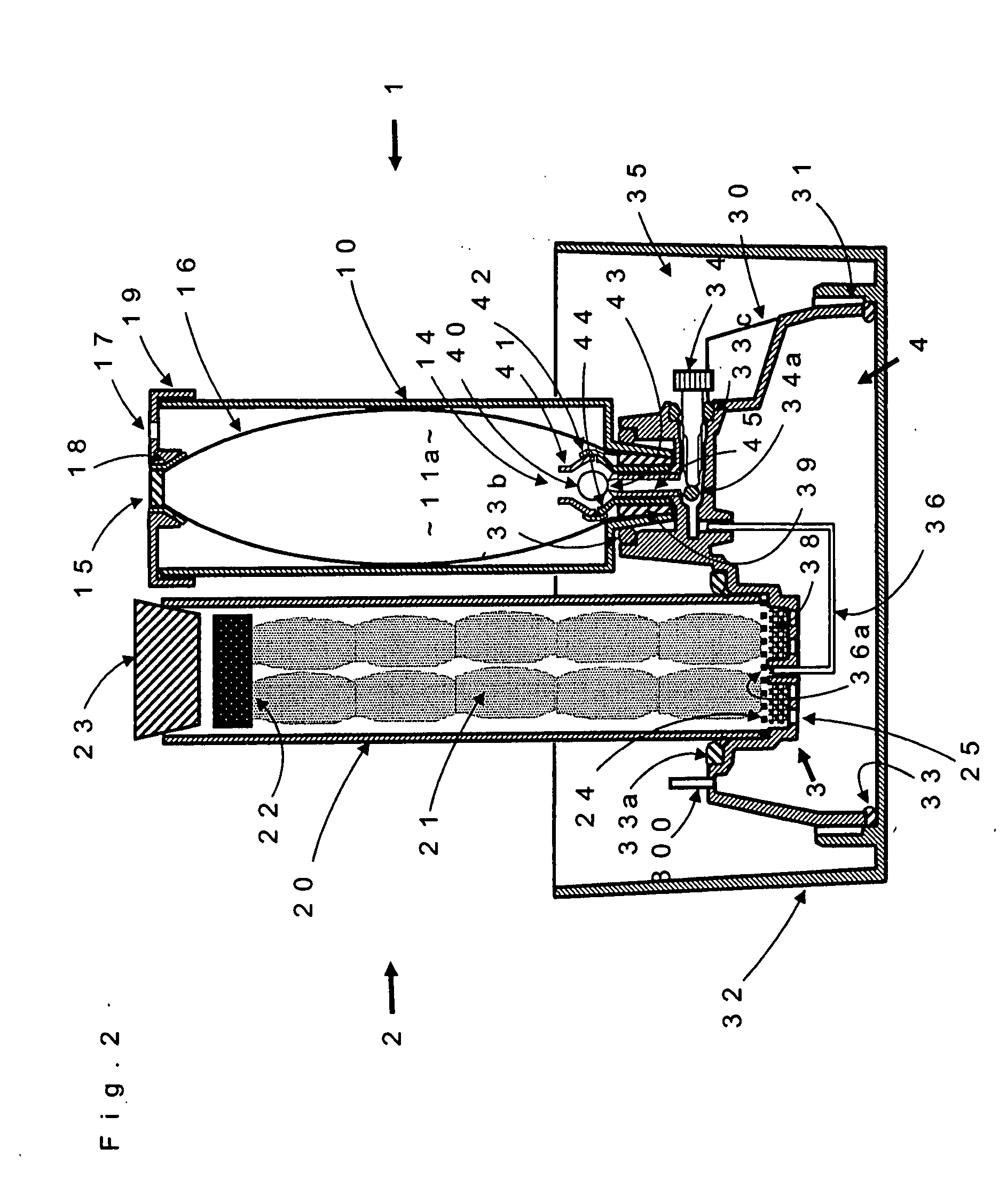
[0022] According to the seventh aspect of the invention described above, it is possible to prevent an abnormal rise in pressure due to the chemical reaction in the device and manually interrupt the chemical reaction by providing a valve arrangement including a first valve structure adapted and arranged to allow said liquid to flow toward said first space during fuel gas generating operation and to prevent reverse flow of said liquid to the inside of said chamber, and a second valve structure having an external operator for opening and closing said system. The two-way valve structure opens the circuit automatically permitting flow of liquid to the first reaction space and closes the circuit so there is no reverse flow when pressure of the chemical reaction is at or above a prescribed pressure. The second valve structure permits optionally starting or stopping the chemical reaction using an external operator.
[0023] According to the eighth aspect of the invention described above, because the weight or elastically deforming member operates to always keep the solid component in contact with the permeable member, malfunctioning of the apparatus due to the solid component being dissolved and adhering to the storage vessel wall to thereby stop movement of the same is prevented. Accordingly, contact between the permeable member and the solid component is maintained and gap formation between the permeable member and the solid component is prevented.
[0024] According to the ninth aspect of the invention, it is possible to visually check for fuel gas leaks by bubbles and the like simply and inexpensively by providing a water storage space on the outer periphery of the device. Such a space may be provided using a structure connected to the exterior of the device using, for example, integral molding of a transparent resin or the like.

Problems solved by technology

A first problem encountered previously with devices such as those described above is that the rate of the fuel gas generating chemical reactions tends to decrease as a function of time as the reaction continues whereby the gas generation rate also falls with time.
One major cause of this when the fuel gas is generated using an oxidation catalyst may be assumed to be a decrease in the effectiveness of the catalyst.
A second problem encountered previously has been the difficulty in providing portable and / or mobile models aimed at popularization.

Method used


Image

  • Fuel gas generation and supply device
  • Fuel gas generation and supply device
  • Fuel gas generation and supply device

Examples


Embodiment Construction

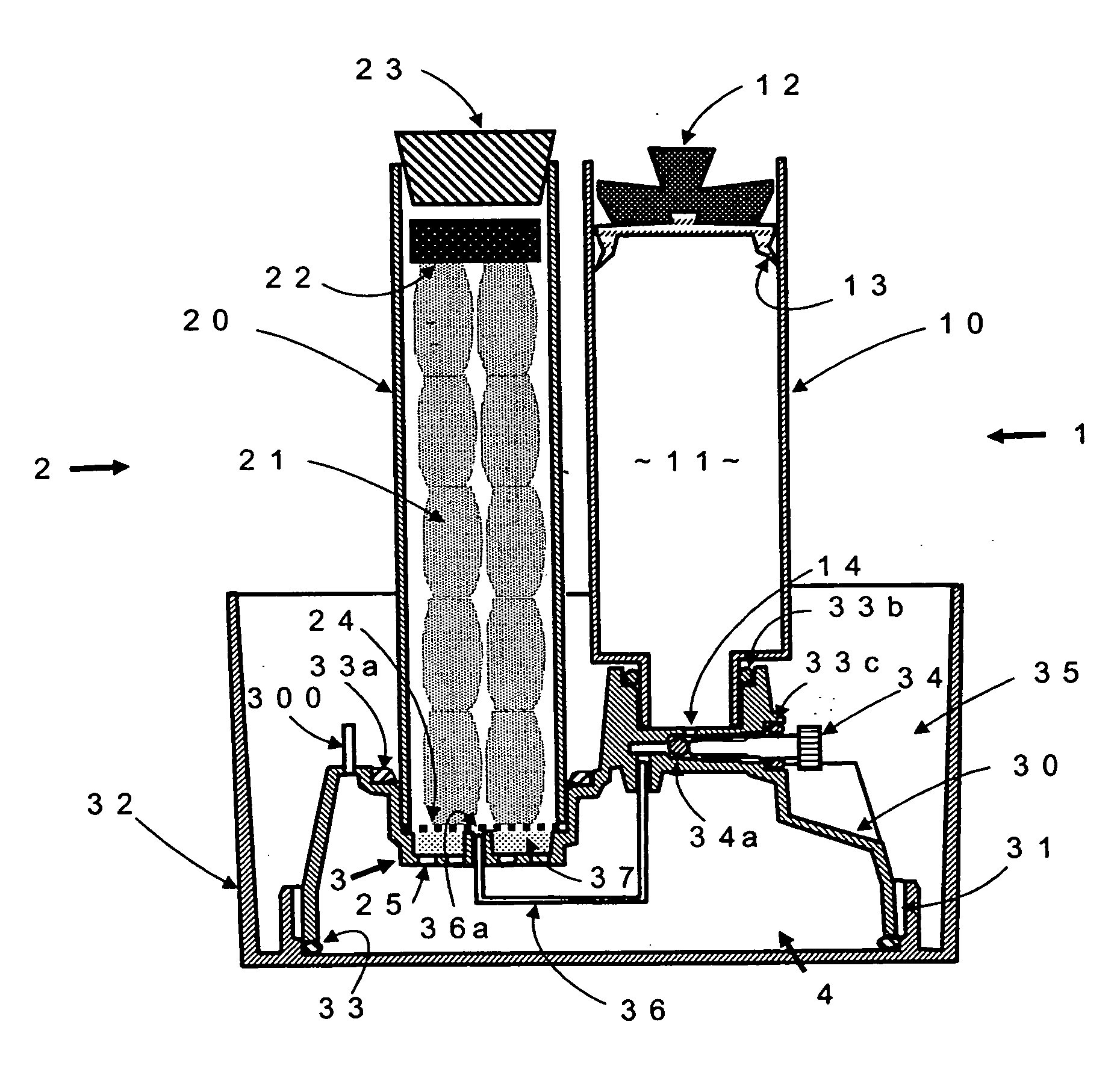
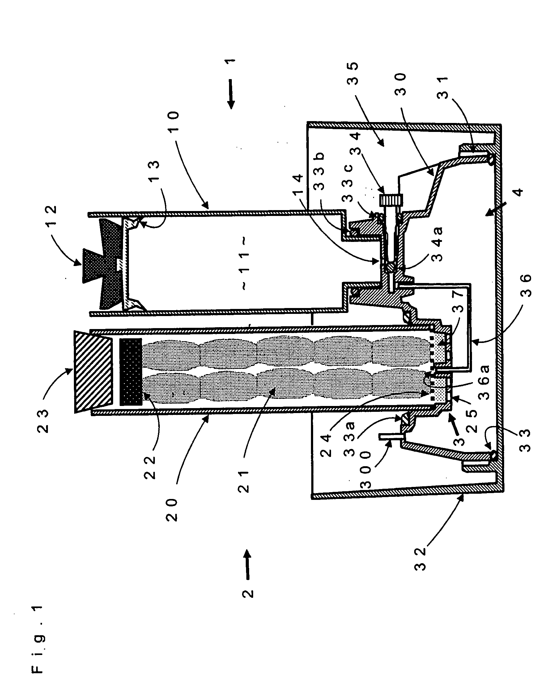
[0031] In the following detailed description, embodiments of the present invention are described with reference to the drawings. In this regard, FIG. 1 is a cross-sectional view illustrating a first embodiment of the present invention. This embodiment comprises a mobile, lightweight generation and supply device that generates and supplies a constant amount of hydrogen for use in a fuel cell or the like using a chemical reaction.

[0032] The gas generation and supply device of the present invention comprises four parts, a liquid storage body 1, a solid component storage body 2, a first chemical reaction space 3 and a second chemical reaction space 4. The storage body 1 comprises a vessel or chamber (for example, a partially or completely transparent body when there is a low-pressure, small volume hydrogen gas supply of approximately 0.1 Pa or less) 10 and a weight 12 provided with a sealing member 13. Vessel 10 stores a catalyst solution (for example, a malic or hydrochloric acid solu...


PUM

PropertyMeasurementUnit
heightaaaaaaaaaa
heightaaaaaaaaaa
pressureaaaaaaaaaa

Abstract

A fuel gas generation device comprises a compartment containing a solid component and a chamber containing a liquid capable of causing a fuel gas generating chemical reaction when in contact with said solid component. A liquid permeable member is disposed between the compartment and the chamber and in contact with said solid component and a liquid supply system is disposed and arranged for delivering liquid from the chamber to the permeable member at a fixed rate. The device also includes a first chemical reaction space adjacent the permeable member where the fuel gas generating chemical reaction occurs and a second chemical reaction space linked to the first space. The volume of the first space is smaller than the volume of the second space. The device is useful for multiple purposes and generates and supplies a constant amount of fuel gas for mobile and portable fuel cells and the like continuously, stably, conveniently and inexpensively without using pressure adjusting valves and the like. The device includes a system capable of being applied to a wide range of uses for amounts of fuel gas. The operation of the device to maintain a constant reaction rate is based on the concentration of an oxidation catalyst material dissolved in the liquid, the performance of a solid oxidation catalyst material, the liquid supply rate, and / or the size of the surface area of a permeable member in contact with the liquid. The device is useful for maintaining a constant chemical reaction rate regardless or whether the oxidation catalyst is in liquid or solid form.

Description

CROSS REFERENCES TO RELATED APPLICATION [0001] None BACKGROUND OF THE INVENTION [0002] 1. Field of the Invention [0003] The present invention relates to gas generation and supply devices for supplying fuel gas to fuel cells continuously and at a constant rate by virtue of causing the underlying chemical reaction to proceed at a constant rate. [0004] 2. The Prior Art Background [0005] Various storage and supply methods have been developed and proposed up to this point as fuel supply means for mobile and portable fuel cells. One attempt, a fuel supply means that makes use of a chemical reaction aimed at practical applications has come to be widely proposed as a lightweight, inexpensive method where the amount of fuel storage is greater than other methods. However, there is an urgent need for providing a practical device capable of continuously and stably supplying a constant amount of fuel gas by means of a chemical reaction that proceeds at a given a constant rate and that is small, ...

Claims


Application Information

Patent Timeline
Patent Type & Authority Applications(United States)
IPC IPC(8): H01M8/04B01J7/00H01M8/18
CPCC01B3/065C01B2203/066Y02E60/50Y02E60/362H01M8/04201Y02E60/36
Inventor KOBAYASHI, KOJI
Owner NK TECH
Learn More