Real-time synchronized control and simulation within a process plant

a technology of process plant and simulation system, which is applied in the field of process plants, can solve the problems of difficult to set up or create a simulation of the process plant or a portion of the process plant, the simulation system is not closely coordinated with the actual operation of the control network within the process plant, and the process model used in the simulation system may quickly diverge from the actual process operation, etc., to achieve the effect of convenient use, easy use and understanding

Active Publication Date: 2008-01-31
EMERSON PROCESS MANAGEMENT POWER & WATER SOLUTIONS
View PDF21 Cites 142 Cited by
  • Summary
  • Abstract
  • Description
  • Claims
  • Application Information

AI Technical Summary

Benefits of technology

[0013]Because the simulation system, when it enters the prediction mode, is synchronized with the actual process control network and the process plant as currently operating, the simulation system provides a more accurate simulation or prediction of the operation of the process plant in response to the control variables used in the simulation. Moreover, because the simulation system is synchronized with the process plant upon activation of the simulation system, th...

Problems solved by technology

None-the-less, only the most complex simulation systems are typically able to perform high fidelity simulation of the process plant because of the ever changing conditions within the plant, including the degradation of devices over time, as well as the presence of unaccounted for disturbance variables within the plant.
Moreover, in many known controller systems, it can be difficult to set up or create a simulation of the process plant or a portion of the process plant as simulation activities are performed separately from the display and control activities performed in the on-line environment of the process plant.
As a result, the simulation system is not closely coordinated with the actual operation of the control network within the process plant.
Moreover, the process model used in the simulation system may quickly diverg...

Method used


Image

  • Real-time synchronized control and simulation within a process plant
  • Real-time synchronized control and simulation within a process plant
  • Real-time synchronized control and simulation within a process plant

Examples


Embodiment Construction

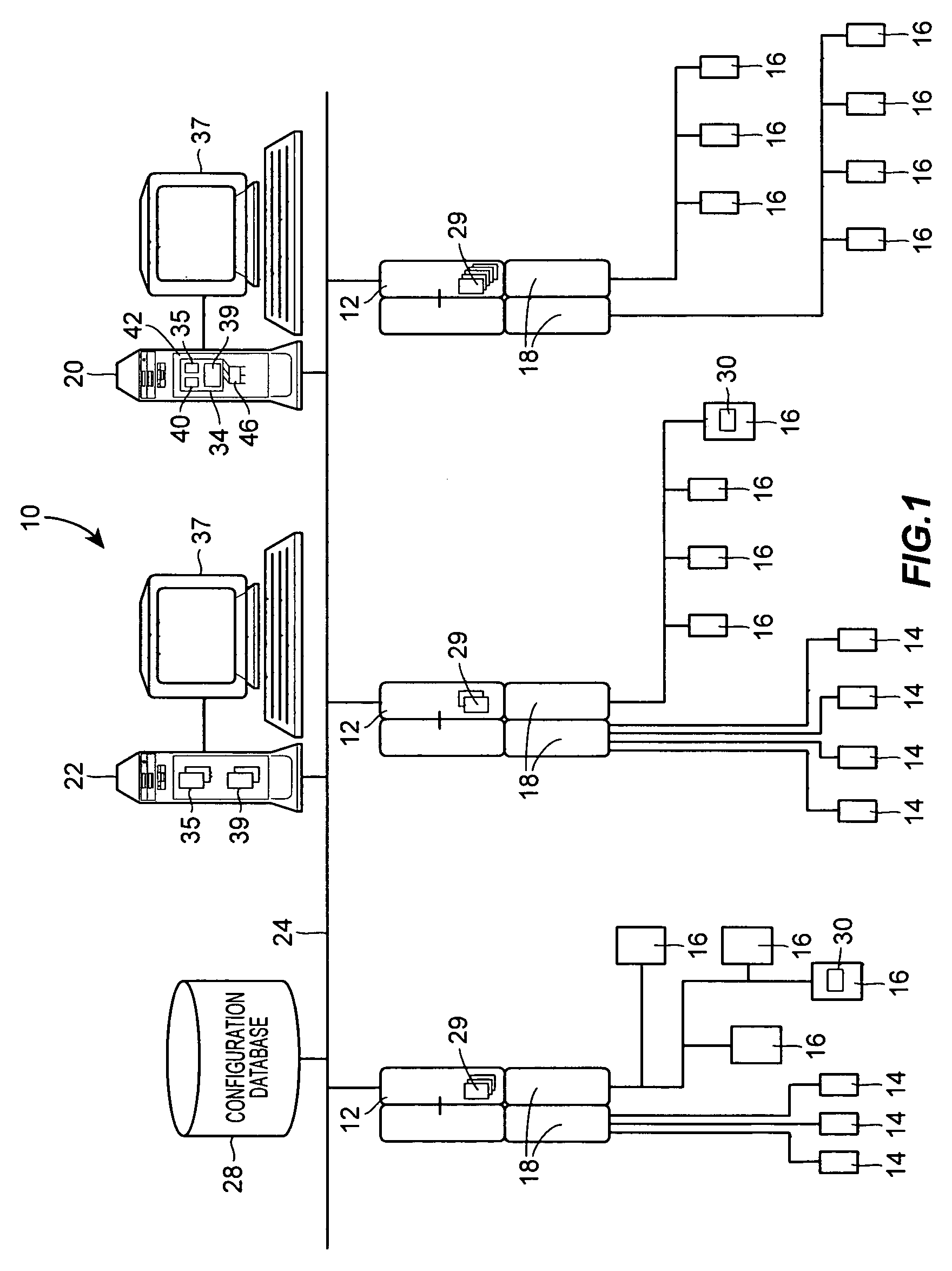
[0020]Referring now to FIG. 1, an example control network for process plant 10, such as that associated with a power generation plant, is illustrated in detail. The process plant 10 of FIG. 1 includes a distributed process control system having one or more controllers 12, each of which is connected to one or more field devices 14 and 16 via input / output (I / O) devices or cards 18 which may be, for example, Fieldbus interfaces, Profibus interfaces, HART interfaces, standard 4-20 ma interfaces, etc. The controllers 12 are also coupled to one or more host or operator workstations 20 and 22 via a data highway 24 which may be, for example, an Ethernet link. A database 28 may be connected to the data highway 24 and operates as a data historian to collect and store parameter, status and other data associated with the controllers 12 and field devices 14, 16 within the plant 10. Additionally or alternatively, the database 28 may operate as a configuration database that stores the current conf...


PUM


Abstract

A process control system simulation technique performs real-time simulation of an actual process control network as that network is running within a process plant in a manner that is synchronized with the operation of the actual process control network. This real-time, synchronized simulation system includes a simulation process control network and a process model which are automatically updated periodically during the operation of the actual process control network to reflect changes made to the process control network, as well as to account for changes in the plant itself, i.e., changes which require an updated process model. The disclosed simulation system provides for more readily accessible and usable simulation activities, as the process control network and the process models used within the simulation system are synchronized with and up-to-date with respect to the current process operating conditions. Moreover, this simulation system is more accurate as it uses process models developed from the current state of the process whenever the simulation system beings to perform a simulation. Still further, the disclosed simulation system is easy to operate, as it uses the same user interface applications as the actual process control network and can be initialized and used at any time during operation the process plant without any significant configuration or set-up activities.

Description

TECHNICAL FIELD[0001]The present invention relates generally to process plants such as power generation and industrial manufacturing plants and, more particularly, to a real-time control and simulation system that performs synchronized simulation of the operation of the control network within the process plant.DESCRIPTION OF THE RELATED ART[0002]Distributed process control systems, like those typically used in power generation, chemical manufacturing, petroleum processing or other process plants, typically include one or more process controllers communicatively coupled to one or more field devices via analog, digital or combined analog / digital buses. The field devices, which may be, for example, valves, valve positioners, switches, transmitters (e.g., temperature, pressure, level and flow rate sensors), burners, etc. are located within the process environment and perform process functions such as opening or closing valves, measuring process parameters, etc. in response to control si...

Claims


Application Information

Patent Timeline
IPC IPC(8): G06F9/45
CPCG05B19/41885G05B13/041Y02P90/02
Inventor KEPHART, RICHARD W.CHENG, XUSCHILLING, STEVEN J.YEAGER, ROBERT L.
Owner EMERSON PROCESS MANAGEMENT POWER & WATER SOLUTIONS
Why Eureka
Try Eureka