
Method and apparatus for fault-tolerant transmission gear selector lever position determination

a technology of gear selector and position determination, which is applied in the direction of mechanical equipment, gearing control, transportation and packaging, etc., can solve the problems of unintended vehicle movement, impracticality of implementing mechanical/hydraulic interlocking systems, etc., and achieve the effect of reducing component costs

Inactive Publication Date: 2008-02-07
GM GLOBAL TECH OPERATIONS LLC +1
View PDF5 Cites 258 Cited by
  • Summary
  • Abstract
  • Description
  • Claims
  • Application Information

AI Technical Summary

Benefits of technology

[0008]It is therefore an object of this invention to provide a method and apparatus capable of fault-tolerant gear selector lever position determination for a transmission, including application in a fuel / electrical hybrid transmission employing a shift-by-wire mechanism. The invention described herein enables continued operation in event of loss of a single control module, i.e. provides a level of redundant controllers; provides fault tolerance, i.e eliminates vehicle disablement and operator walk-home; eliminates safety-critical faults; works with existing controllers having pre-defined input / output (‘I / O’) circuitry designed for sliding contact switches; reduces component costs, by allowing the use of inexpensive digital switches in place of redundant analog sensors; and, enables critical packaging constraints of front wheel drive (‘FWD’) valve body to be achieved by removal of a hydraulic manual valve.

Problems solved by technology

Determination of transmission gear selector lever position is deemed safety-critical, as a fault may cause vehicle movement to be commanded in an unintended direction.
Implementing a mechanical / hydraulic interlock system may be impractical due to an inability to provide the needed functionality and packaging constraints.

Method used


Image

  • Method and apparatus for fault-tolerant transmission gear selector lever position determination
  • Method and apparatus for fault-tolerant transmission gear selector lever position determination
  • Method and apparatus for fault-tolerant transmission gear selector lever position determination

Examples


Embodiment Construction

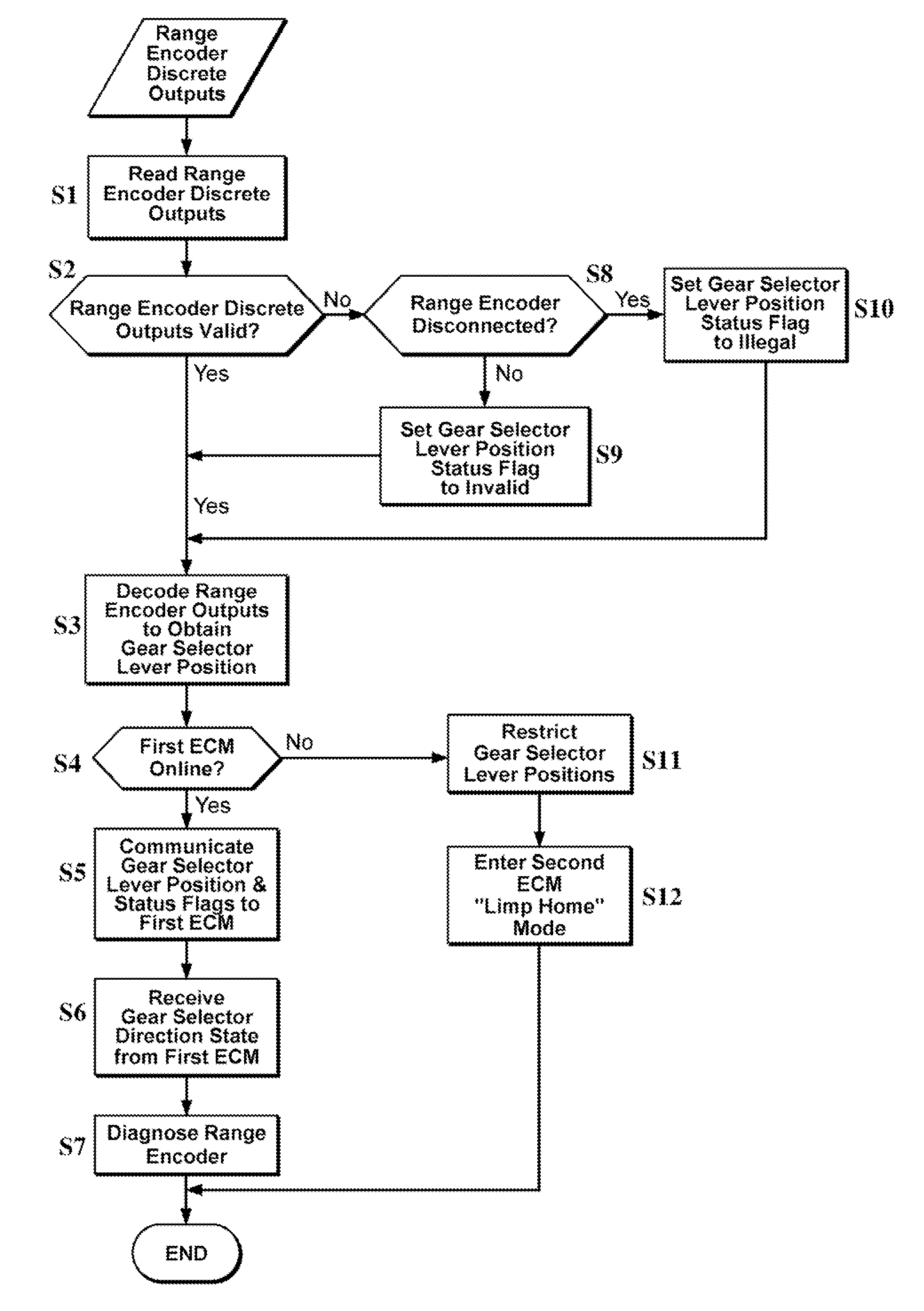
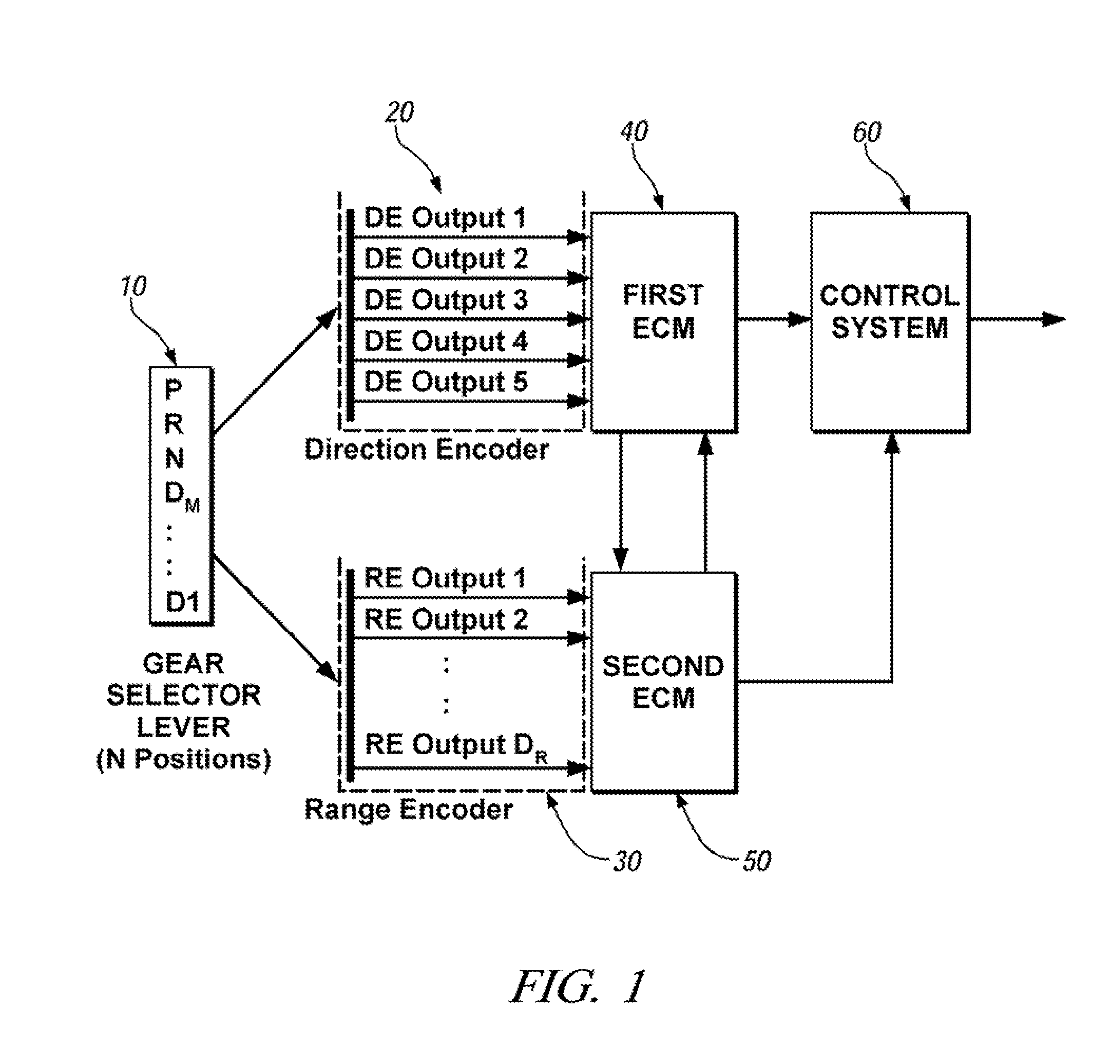
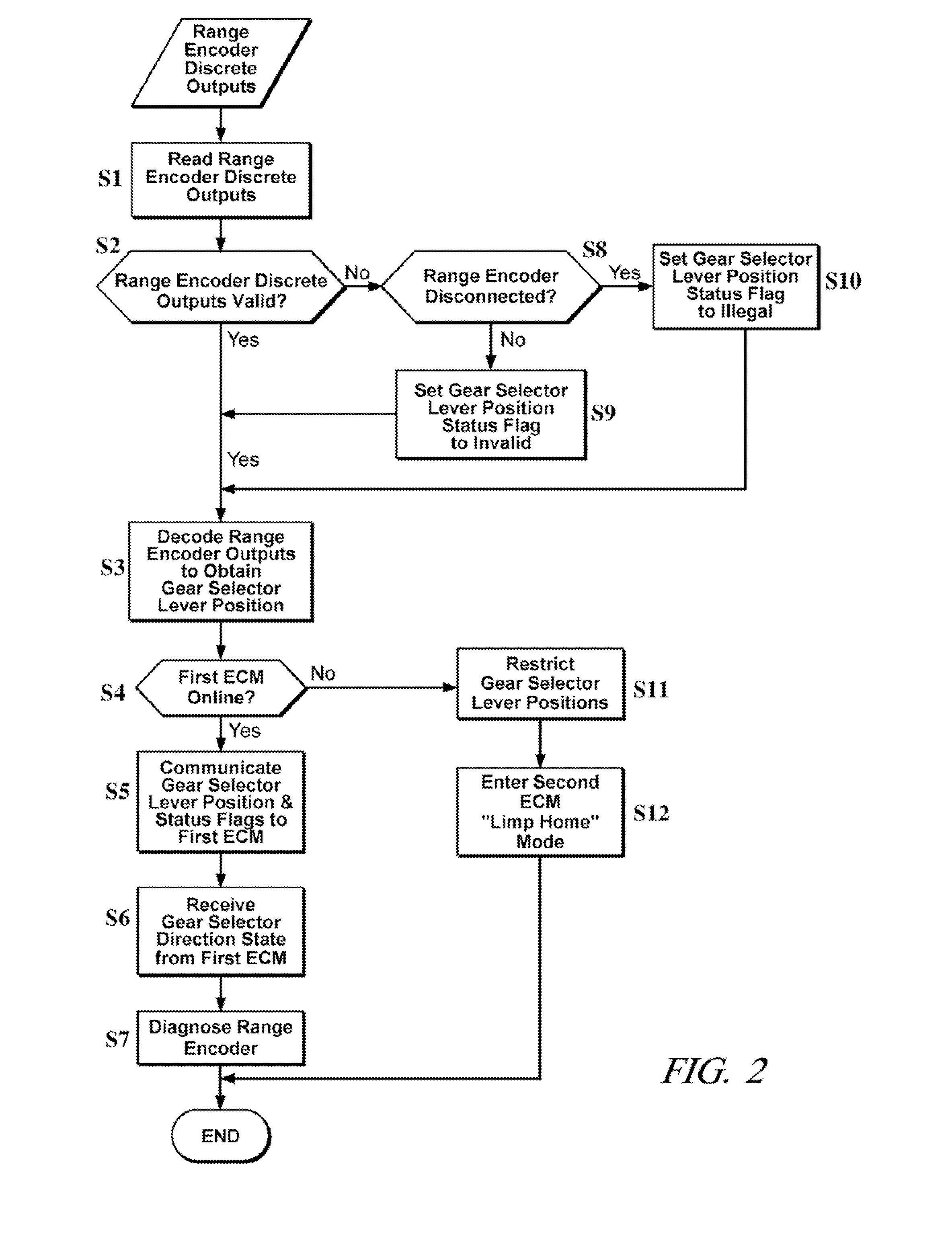
[0018]Referring now to the drawings, wherein the showings are for the purpose of illustrating the invention only and not for the purpose of limiting the same, FIG. 1 shows a schematic diagram of an apparatus for fault-tolerant hardware and software architecture for determining position of a gear selector lever for a power transmission device, as can be applied on a motorized vehicle, that has been constructed in accordance with an embodiment of the invention. The exemplary system includes a transmission gear selector lever 10 having a discrete number of operator-selectable positions. First and second gear selector lever position sensors 30, 20 are operatively attached thereto. Signal output from the first gear selector lever position sensor 30 is output to a second electronic control module 50. Signal output from the second gear selector lever position sensor 20 is output to a first electronic control module 40. The first and second electronic control modules 50, 40 have bi-directio...


PUM


Abstract

A fault-tolerant gear selector lever position apparatus is described. Included is a first sensor operable to detect each position, and a second sensor operable to detect subsets of the positions. A first controller monitors the second sensor, and a second controller monitors the first sensor. The second controller identifies and communicates one of the positions to the first controller, and the first controller validates the position and communicates the position to a control system. The lever is applicable to a power transmission device. Each sensor preferably comprises digital encoding sensor; the first sensor generates a unique signal for each position, and the second sensor generates a unique signal for each subset of the positions, preferably a unique signal for each of Park, Reverse, Neutral, and Forward Drive. The controllers identify faults in the sensors, and communicate and act accordingly.

Description

CROSS-REFERENCE TO RELATED APPLICATIONS[0001]This application claims priority from U.S. Provisional Application No. 60 / 703,913, filed Jul. 29, 2005, entitled METHOD AND APPARATUS FOR FAULT-TOLERANT TRANSMISSION SHIFT LEVER POSITION.TECHNICAL FIELD[0002]This invention pertains generally to vehicle transmission systems, and more specifically to an apparatus and method for fault-tolerant transmission gear selector lever position determination.BACKGROUND OF THE INVENTION[0003]Designers of transmission systems for use in motor vehicles are required to implement a transmission gear selector lever having a minimum of four positions, or ranges, in a sequence of Park, Reverse, Neutral, and Forward Drive, as specified in the Federal Motor Vehicle Safety Standards (49 C.F.R. 571). This includes a further requirement that any transmission having more than one forward gear ratio must provide an additional gear position to enable engine braking. Most modern applications include at least five posi...

Claims


Application Information

Patent Timeline
IPC IPC(8): F16H61/00
CPCF16H59/105F16H61/12F16H2061/1208Y10T74/19251F16H2061/1284Y10S477/906F16H2061/1232
Inventor ROBINETTE, RICHARD E.WU, PETER E.
Owner GM GLOBAL TECH OPERATIONS LLC
Learn More