Sleeve, sleeve unit, motor, and method for manufacturing sleeve and sleeve unit

a technology of sleeve and housing, which is applied in the direction of recording information storage, record carrier contruction details, instruments, etc., can solve the problems of sleeve from the sleeve housing, and achieve the effect of preventing the sleeve from being displaced

a technology of sleeve and housing, which is applied in the direction of recording information storage, record carrier contruction details, instruments, etc., can solve the problems of sleeve from the sleeve housing, and achieve the effect of preventing the sleeve from being displaced

US20080029212A1Inactive Publication Date: 2008-02-07NIPPON DENSAN CORP

Image

  • Sleeve, sleeve unit, motor, and method for manufacturing sleeve and sleeve unit
  • Sleeve, sleeve unit, motor, and method for manufacturing sleeve and sleeve unit
  • Sleeve, sleeve unit, motor, and method for manufacturing sleeve and sleeve unit

Examples


Embodiment Construction

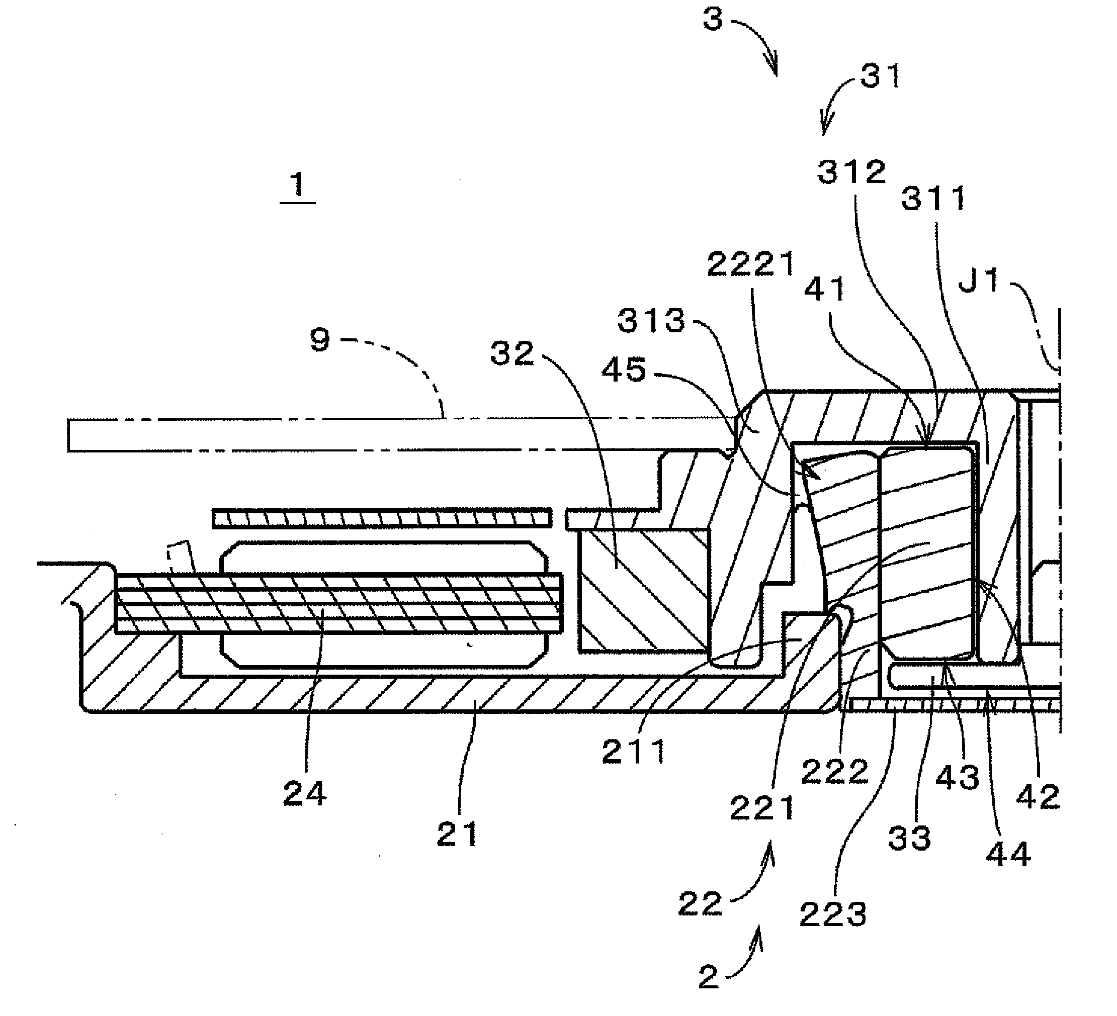
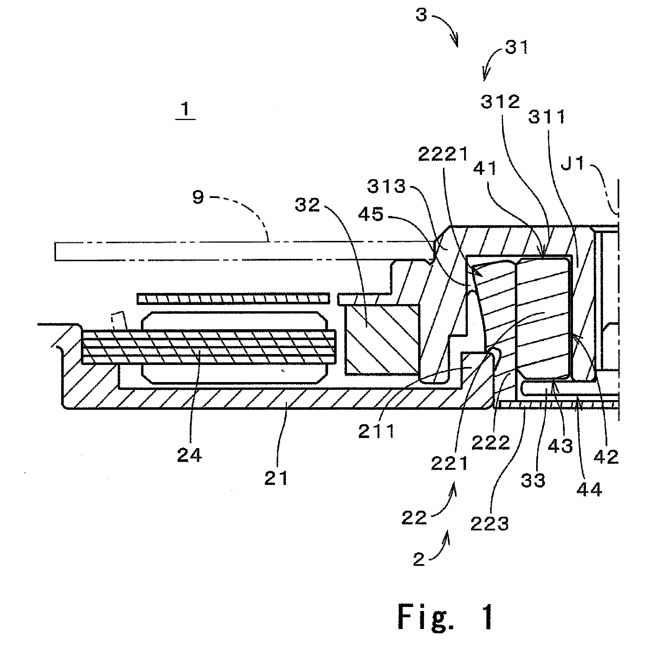
[0043]FIG. 1 is a vertical cross sectional view of a motor 1 for driving a data storage disk according to a preferred embodiment of the present invention. FIG. 1 illustrates only a left half of a cross section of the motor 1 including a central axis J1 (which is also a central axis of a sleeve unit 22 to be described later).

[0044]The motor 1 includes a static portion 2 as a stator assembly and a rotor portion 3. The rotor portion 3 is supported by the static portion 2 via a bearing assembly utilizing fluid dynamic pressure of lubricant so as to rotate around the central axis J1. It is noted that, in the description of the present invention, positional relations and directions of respective members described as up, down, left, and right simply indicate positional relations and directions in the drawings, and do not indicate positional relations and directions when actually incorporated in equipment.

[0045]The rotor portion 3 includes a rotor hub 31 and a rotor magnet 32. A center of t...


PUM

PropertyMeasurementUnit
Pressureaaaaaaaaaa
Angleaaaaaaaaaa
Widthaaaaaaaaaa

Abstract

Adhesive is applied to an inner surface of a sleeve housing, and a sleeve is inserted from a lower end part thereof into the sleeve housing. An outer edge of the lower end part of the sleeve is provided with an adhesive holding portion in a chamfered shape, and a part of the adhesive is held between the adhesive holding portion and the inner surface of the sleeve housing.

Description

BACKGROUND OF THE INVENTION[0001]1. Field of the Invention[0002]The present invention relates to a technique for manufacturing a sleeve unit for a motor, with a sleeve provided in a sleeve housing.[0003]2. Description of Related Art[0004]Conventionally, a data storage disk drive unit such as a hard disk device includes a spindle motor (hereinafter, simply referred to as “motor”) for rotary driving a data storage disk. A bearing assembly utilizing fluid dynamic pressure is adopted as one of motor bearing assemblies. In such a bearing assembly utilizing fluid dynamic pressure, a thrust bearing portion or a radial bearing portion are defined with a shaft, a sleeve to allow the shaft to be inserted thereinto, and the like.[0005]For example, Japanese Unexamined Patent Publication No. 2003-262217 discloses a bearing assembly in which a sleeve is inserted into a sleeve housing and a thrust plate is provided at a distal end of a shaft. This bearing assembly is provided with thrust bearing p...

Claims


Application Information

Patent Timeline
07 Feb 2008
Publication
US20080029212A1
IPC
B29C65/52; B21K1/00
CPC
B21J5/12; Y10T29/49639; B22F5/106; B22F2003/245; B22F2998/10; G11B19/2009; G11B25/043; G11B33/123
Inventors
TAMAOKA, TAKEHITO