Electronic pressure-sensitive device for detecting the magnitude of load as electrical resistance

a technology of electrical resistance and electronic pressure, which is applied in the direction of instruments, pedestrian/occupant safety arrangements, force/torque/work measurement apparatus, etc., can solve the problems of high cost, difficult to detect a small load applied to the electronic pressure-sensitive device or a variation of load, and the inability to sense the physique of the person sitting

Inactive Publication Date: 2002-05-16
ALPS ALPINE CO LTD
View PDF0 Cites 13 Cited by
  • Summary
  • Abstract
  • Description
  • Claims
  • Application Information

AI Technical Summary

Benefits of technology

[0013] Further, since there is no need to maintain a gap between the contact portions, there is no need to provide a maintaining member for maintaining a gap, and there is no deterioration in performance due to deformation of the maintaining member. Further, since there is no gap between the contact portions, the amount of deformation (deflection amount) due to the load is small, so that there is little burden on the substrates, thereby providing a long service life.
[0040] In this electronic pressure-sensitive device, power supply from the outside to the contact portions and the resistance value output between the first and second contact points (power output in accordance with the resistance value) are effected by using the wiring pattern, so that there is no need to separately connect a lead wire or the like to the resistive elements, so that the construction is simple, and it is possible to make the electrical connection between the contact portions and the exterior more reliable.

Problems solved by technology

However, in the conventional electronic pressure-sensitive device, which is turned ON when a load of a magnitude not less than a threshold value is applied, it is difficult to detect a small load applied to the electronic pressure-sensitive device or variation in the load.
In a motor-vehicle-mounted seat sensor using this conventional electronic pressure-sensitive device, it is difficult to detect the magnitude of a load, so that it is impossible to sense the physique of the person sitting on the seat, to operate the air bag in conformity with the physique of the person sitting on the seat, some other device is necessary.
Further, in the case of a motor-vehicle-mounted sensor, a load can be continuously applied at high temperature, so that it is necessary to use an expensive material such as polyethylene terephthalate, which has a superior heat resistance, for the first and second insulating substrates 51 and 55, which are continuously deflected by the load (baggage), resulting in a high cost.

Method used


Image

  • Electronic pressure-sensitive device for detecting the magnitude of load as electrical resistance
  • Electronic pressure-sensitive device for detecting the magnitude of load as electrical resistance
  • Electronic pressure-sensitive device for detecting the magnitude of load as electrical resistance

Examples


Embodiment Construction

[0079] FIG. 5 is a sectional view of an electronic pressure-sensitive device as a comparative example.

[0080] Like the embodiments of the present invention, the comparative example comprises first and second substrates 21 and 25, and first and second contact portions 22 and 26 formed on the first and second substrates 21 and 25 and opposed to each other. The first and second contact portions 22 and 26 are of a double layer structure, consisting of first and second conductor layers 22a and 26a and first and second resistive element layers 22b and 26b. The first resistive element layer 22b and the second resistive element layer 26b are opposed to each other through the intermediation of a gap S as long as no load is applied to the substrates 21 and 25, the width of the gap S being maintained by the thickness dimension of a spacer 24 provided between the first and second substrates 21 and 25.

[0081] Next, the load-resistance characteristics of the electronic pressure sensitive device of ...


PUM

PropertyMeasurementUnit
diameteraaaaaaaaaa
thicknessaaaaaaaaaa
thicknessaaaaaaaaaa

Abstract

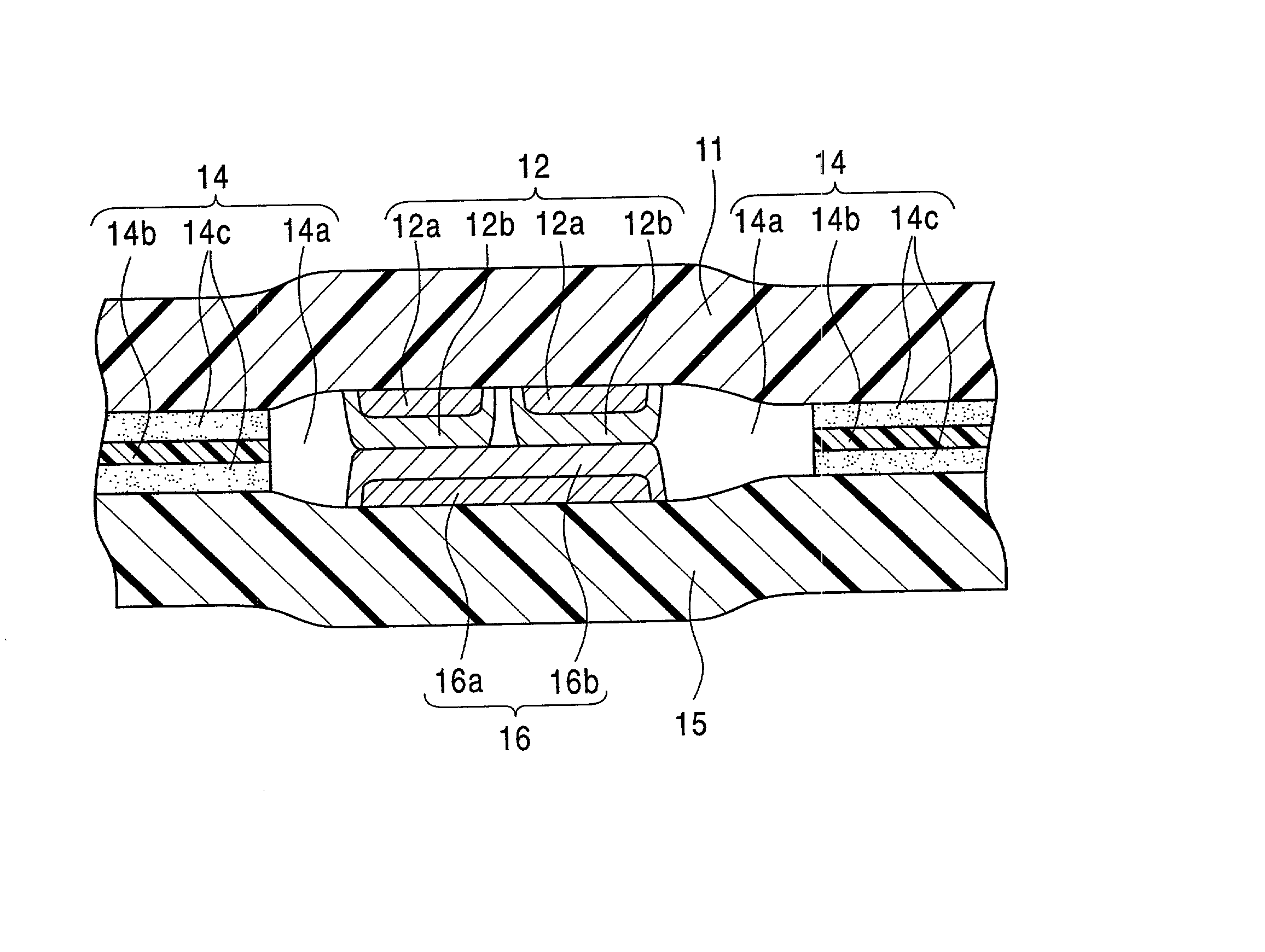
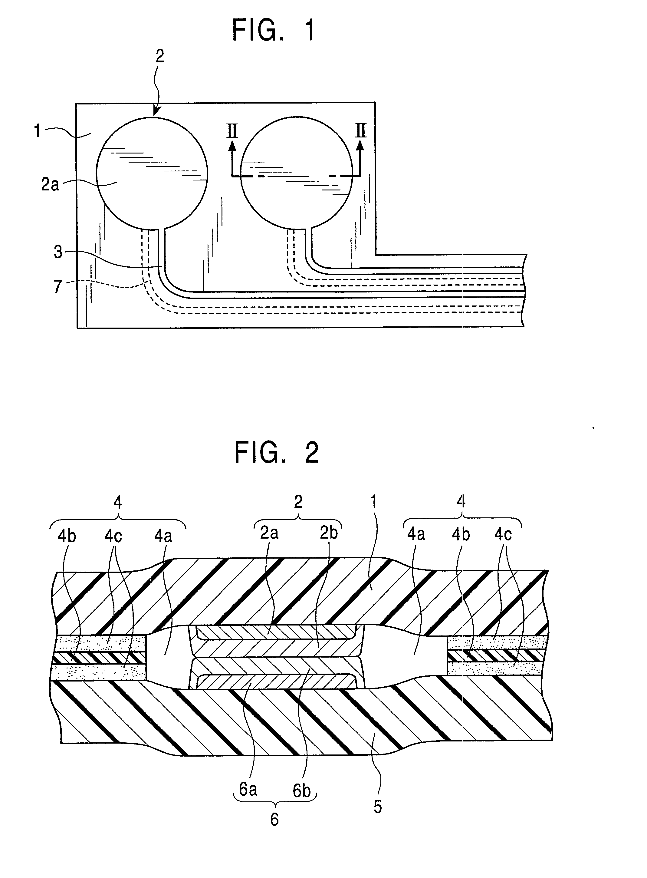
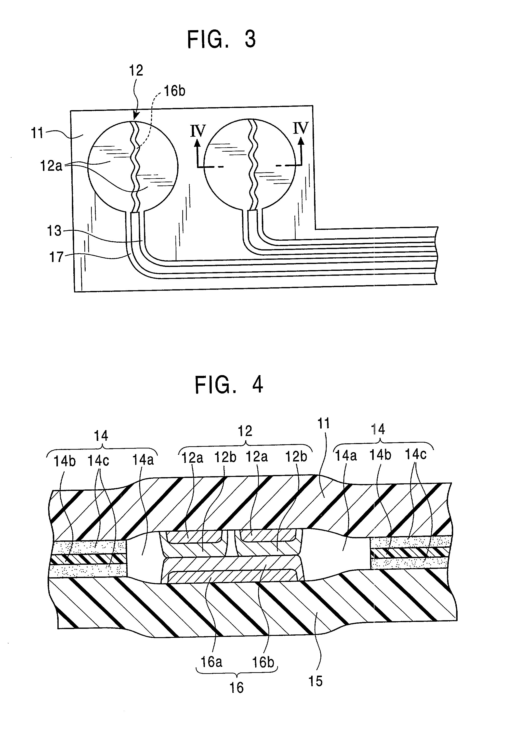
Disclosed is an electronic pressure-sensitive device which has a long service life and which is capable of detecting with high accuracy loads of various magnitudes including values in proximity to zero. In the electronic pressure-sensitive device, first and second resistive element layers 2b and 6b are formed on the outermost surfaces of first and second contact portions 2 and 6, and the first and second resistive element layers 2b and 6b are constantly maintained in an electrical contact state, the force bringing the first and second resistive element layers 2b and 6b into press contact with each other being detected as the electrical resistance between the first and second contact portions 2 and 6.

Description

[0001] 1. Field of the Invention[0002] The present invention relates to an electronic pressure-sensitive device for detecting the magnitude of a load as electrical resistance and, in particular, to an electronic pressure-sensitive device capable of detecting the magnitude of a load ranging from a small load to a large load.[0003] 2. Description of the Related Art[0004] For example, as shown in FIG. 7, in a conventional electronic pressure-sensitive device used in a seat sensor or the like detecting whether a person is sitting on a seat, a first contact portion 52 formed on a flexible first insulating substrate 51 and consisting of a conductive material is opposed to a second contact portion 56 formed on a flexible second insulating substrate 55 and consisting of a conductive material through the intermediation a gap, the width of the gap being maintained by a spacer 54 provided between the first and second insulating substrates.[0005] When a load is applied to the first and second i...

Claims


Application Information

Patent Timeline
Patent Type & Authority Applications(United States)
IPC IPC(8): B60R21/01G01G3/12G01G19/414G01L1/20G01L5/00
CPCG01G19/4142G01G3/12
Inventor SAITO, MITSURU
Owner ALPS ALPINE CO LTD
Why Eureka
Try Eureka