High-power electrical quick connector

a technology of high-power electrical and quick connection, which is applied in the direction of coupling device connection, conductor screwing into other, contact member manufacturing, etc., can solve the problems of poor electrical inability to connect quickly, and inadvertent stress applied by the operator to the connection between the weld cable and the power source, etc., to achieve the effect of quick connection

Inactive Publication Date: 2008-02-07
ILLINOIS TOOL WORKS INC
View PDF8 Cites 4 Cited by
  • Summary
  • Abstract
  • Description
  • Claims
  • Application Information

AI Technical Summary

Problems solved by technology

An operator may inadvertently apply stresses to the connection between the weld cable and the power source during repositioning of the weld cables.
Inadvertent overstressing of the connection can result in poor electrical connectivity between the weld cable and the power source.
Poor electrical connectivity between the weld cable and the power source can detract from weld quality and result in wear between the components of the connection.
Ultimately, the connection can be overstressed to a point of mechanical failure or disengagement.
While some connectors provide a relatively robust mechanical connection, such as by bolting the weld cable to the power source, such constructions are not without their drawbacks.
Specifically, welding-type devices that require the weld cable be bolted to the power source detract from the ease of portability of such devices and the interchangeability of weld cables.
As such, in highly dynamic applications where the power source may be relocated several times a day or welding processes may be required at different distances from the welding device, repeatedly disconnecting and reconnecting the weld cables decreases the overall efficiency of welding operations.
As the amount of current passed through the connection increases, the temperature of the components of the connection also increases and is indicative of power loss associated with the connection.
Heat generated in the connection decreases the electrical efficiency of the connection.
Additionally, if left unaddressed, the temperature of the connector can ultimately lead to failure of the connection or damage to other components of the welding-type device including the welding cables, the torch, the welding device housing, or the internal components of the welding-type device.
As such, the connection between the weld cable and the power source may not only decrease the overall efficiency of the welding-type device but may also define a limit for the amount of welding power that can be communicated through the connection.

Method used


Image

  • High-power electrical quick connector
  • High-power electrical quick connector
  • High-power electrical quick connector

Examples


Embodiment Construction

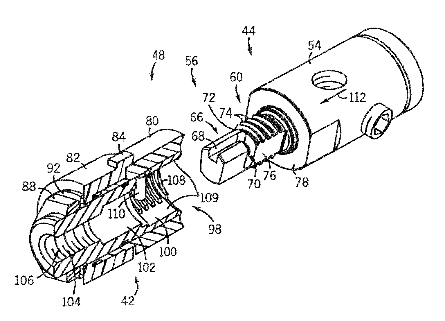
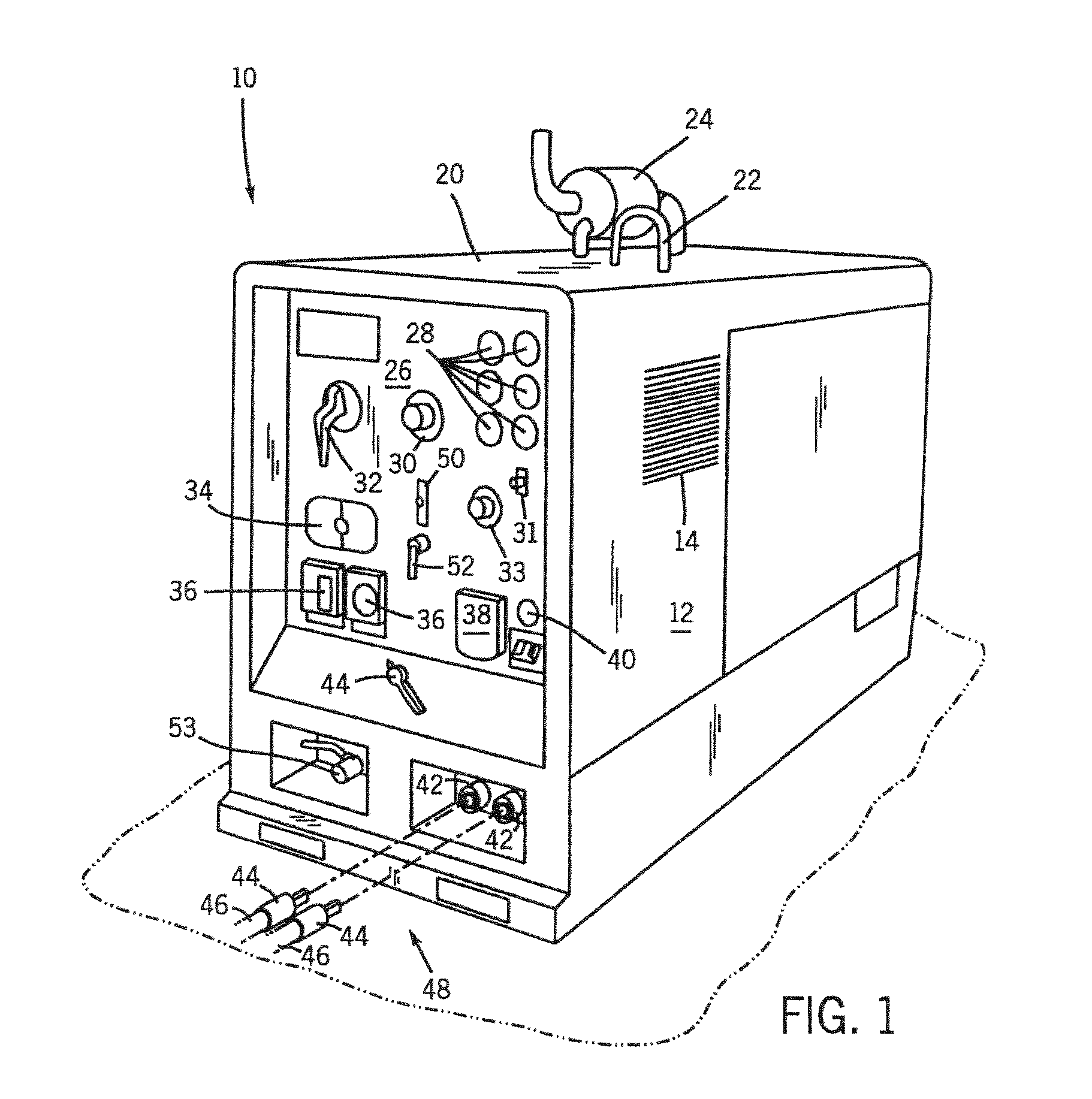
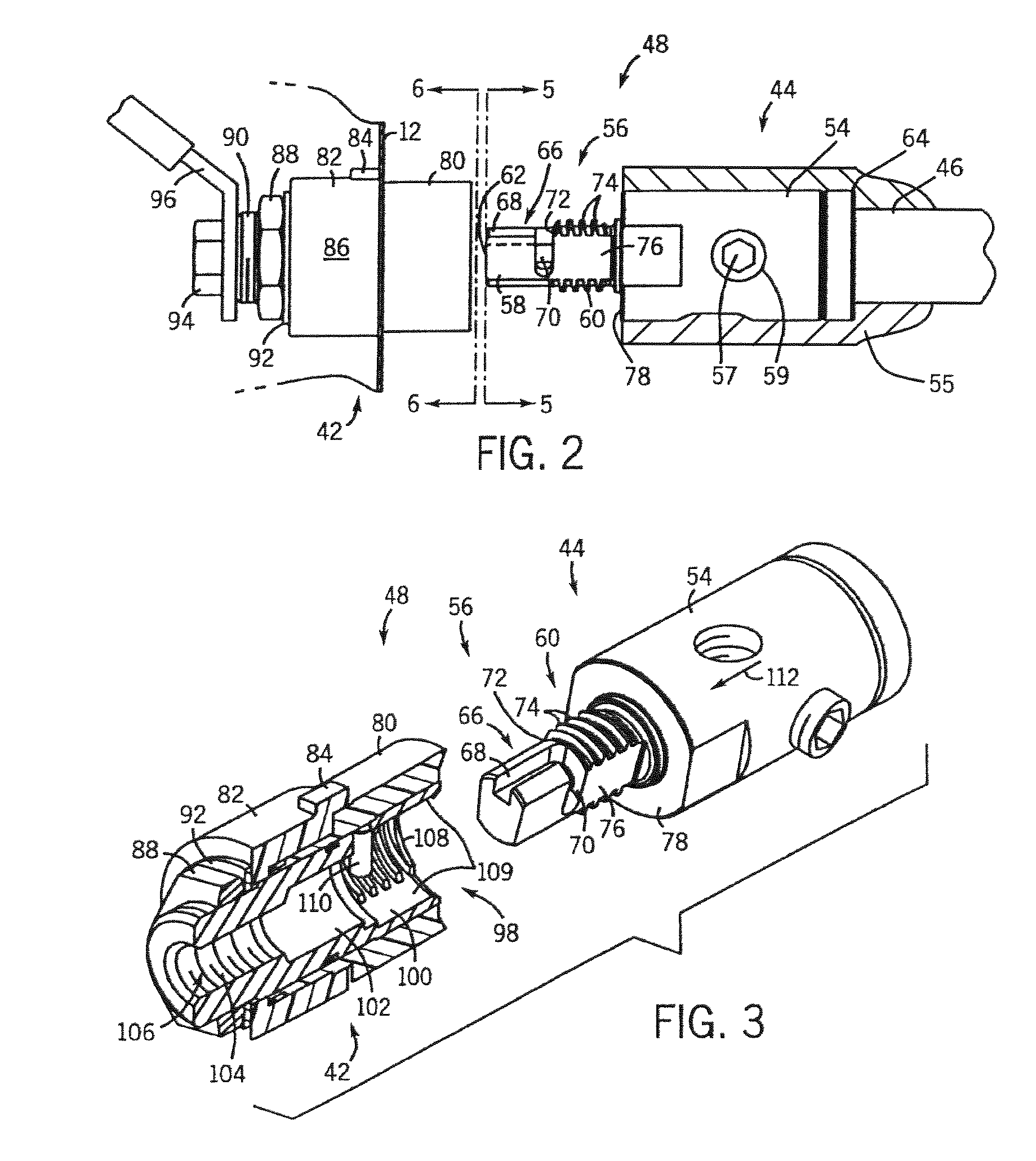
[0036] The present invention will be described with reference to a welder; however, it is understood that its application is not so limited. Referring now to FIG. 1, a portable engine-driven welder system 10 is provided and, for brevity, will hereinafter be referred to as the welding device 10. As one skilled in the art will fully appreciate, the heretofore description of welding devices not only includes welders, but also includes any system that requires high power outputs, such as heating and cutting systems. Therefore, the present invention is equivalently applicable with any device requiring high power output, including welders, plasma cutters, induction heaters, aircraft ground power units, and the like. Reference to welding power, welding-type power, or welders generally, includes welding, cutting, heating power, or ground power for aircraft. Description of a welding apparatus illustrates just one embodiment in which the present invention may be implemented. The present inven...


PUM

PropertyMeasurementUnit
rotationaaaaaaaaaa
rotationaaaaaaaaaa
insertion to engagement rotationaaaaaaaaaa

Abstract

A quick connector assembly for high power electrical applications and method of manufacturing a high-power quick connector assembly are disclosed. The quick connector assembly has a first connector and a second connector constructed to form an electrical connection that can be quickly coupled and decoupled. The first connector has a collar portion connectable to a welding cable and a stem portion having a shank section and a threaded section. The second connector has a recess constructed to receive the stem portion of the first connector and electrically engage both the shank portion and the threaded portion of the first connector.

Description

CROSS REFERENCE TO RELATED APPLICATION [0001] The present application is a divisional and claims priority of U.S. patent application Ser. No. 10 / 711,475 filed Sep. 21, 2004, the disclosure of which is incorporated herein.BACKGROUND OF THE INVENTION [0002] The present invention relates generally to welding-type devices, and more particularly, to a quick connector assembly for use therewith. [0003] Welding-type devices generally have a power source configured to generate a power signal suitable for welding-type applications. This power signal is transmitted beyond the power source by connecting a pair of cables to the power source. One of the cables has a torch at an end thereof and another cable has a work clamp attached at an end thereof. The cables are of such length as to allow an operator to position the torch and work clamp proximate the work piece. Additionally, the cables provide an operator with flexibility in the positioning the work piece relative to the power source. [0004...

Claims


Application Information

Patent Timeline
Patent Type & Authority Applications(United States)
IPC IPC(8): H01R13/73H01R43/16
CPCB23K9/32B23K9/323H01R4/54Y10T29/49204H01R13/213H01R13/53H01R31/06H01R4/56
Inventor BANKSTAHL, HERBERT A.
Owner ILLINOIS TOOL WORKS INC
Why Eureka
Try Eureka