Vascular sheaths and methods for their deployment

a technology of vascular sheaths and sheaths, which is applied in the field of medical methods and equipment, can solve the problems of tissue surrounding the tract to fibrose and resistance to healing, and achieve the effect of minimizing the profile of the access system

Inactive Publication Date: 2008-02-07
PERCUTANEOUS SYST
View PDF35 Cites 113 Cited by
  • Summary
  • Abstract
  • Description
  • Claims
  • Application Information

AI Technical Summary

Benefits of technology

[0028]The systems of the present invention may further comprise a hemostatic connector, such as a Touhy-Borst valve which can removably attach or connect to the proximal end of the sheath. Typically, the hemostatic connector will include an axial branch for receiving an access or other catheter which is to be passed coaxially through the sheath, and at least a second branch coupled or otherwise connected to an annular region between an outside wall of the catheter (one present in the sheath) and an inside wall of the sheath. Usually, the catheter will provide a non-collapsible lumen which is suitable for both aspiration and introductions of materials to the body lumen. The annular region created within the sheath is usually suitable for the introduction of pressurized fluids, where in the absence of a pressurized fluid the sheath will collapse on itself or on to the catheter (one present) in order to minimize the profile of the access system when indwelling in the blood vessel or other body lumen.
[0029]The introducer of the systems of the present invention may comprise a tube or other elongate member adapted to advance the thin-walled, collapsible sheath into the blood vessel or other body lumen. An elongate member will typically have a proximal end and a distal end, where the member may be positioned in the sheath and have a distal end frangibly connected to a location on the elongate member near its distal end. Such frangible connection will be capable of being broken or selectively detached in a variety of ways. Typically, the elongate member and sheath may be connected by adhesives, thermal bonding, the use of staples or other fasteners, or the like. Such connections may be broken by tensioning the connection, for example by axially advancing or torqueing the elongate member relative to the sheath. Alternatively, the connection may be broken by exposure to the luminal environment, for example by allowing the connection to dissolve in a fairly short period of time, or by the application of energy, such as electrical energy, ultrasonic energy, or the like.

Problems solved by technology

In such techniques, repeated percutaneous access through the same tract and tissue causes the tissue surrounding the tract to fibrose, and over time become resistant to healing.

Method used


Image

  • Vascular sheaths and methods for their deployment
  • Vascular sheaths and methods for their deployment
  • Vascular sheaths and methods for their deployment

Examples


Embodiment Construction

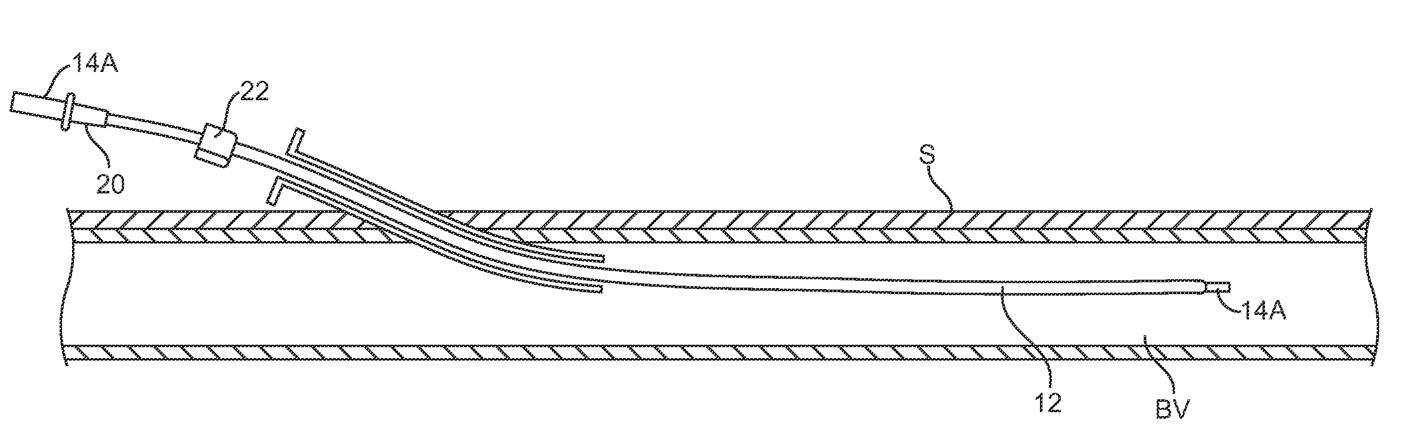
[0044]Systems and methods according to the present invention provide minimally invasive and minimally traumatic access to blood vessels and other body lumens. Blood vessels may be arteries or veins, and other body lumens include the peritoneum for peritoneal dialysis, the gastrointestinal tract, and the like. Percutaneous refers to passing a sheath and optionally catheter of the system through the patient's skin into the blood vessel or other body lumen beneath a layer of tissue under the skin.

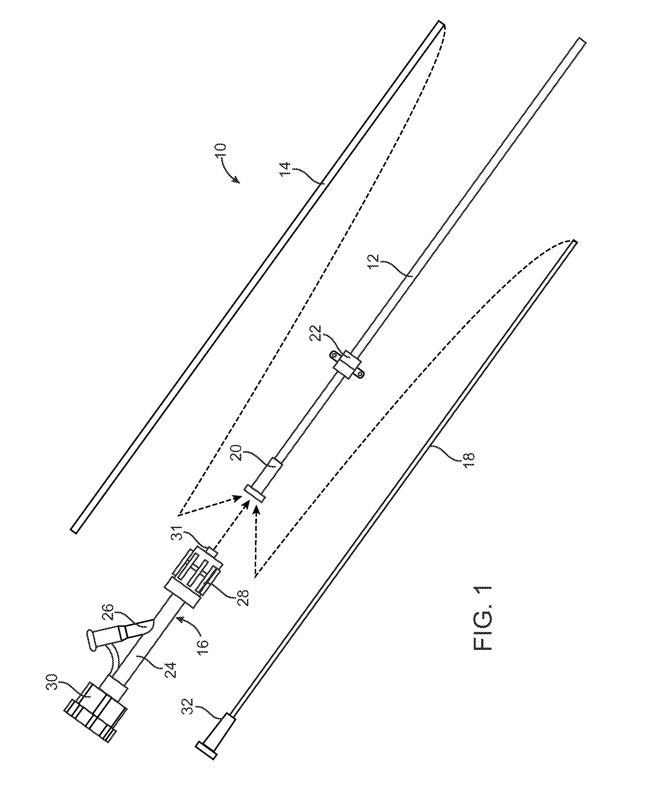
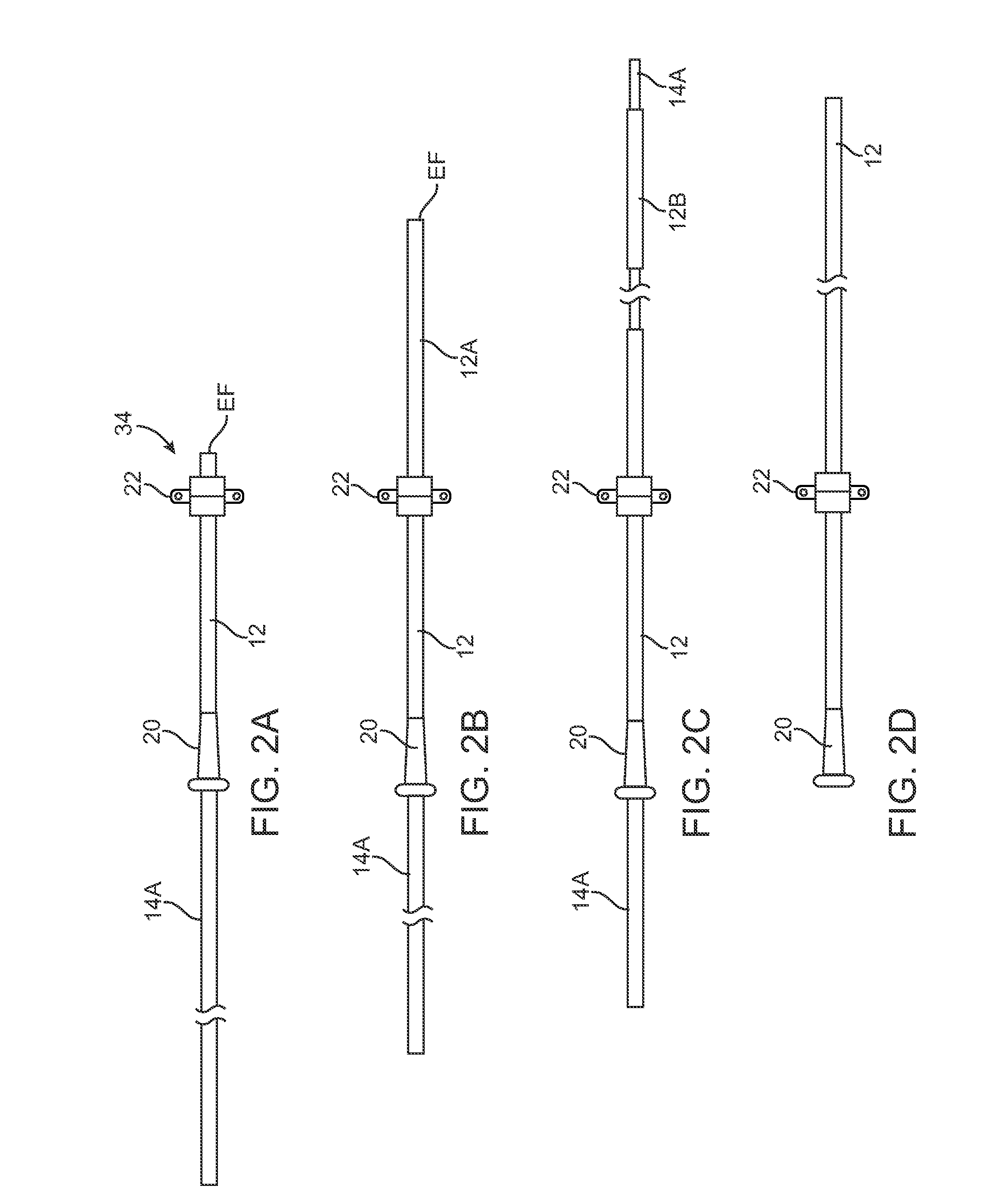
[0045]Systems of the present invention will comprise at least the sheath and an introducer for positioning or advancing the sheath through the skin penetration to the target body lumen. As the sheath will often be left in place for extended periods of time, often days, weeks, or even longer, the sheath will preferably have an anchor or attachment to the skin. The sheath will also usually include a luer or other connector at or near its proximal end to permit attachment to a fluid source, a hem...


PUM


Abstract

A percutaneous luminal access system comprises a thin-walled, collapsible sheath, an introducer, a hemostatic valve, and an access catheter. An introducer may comprise either a pusher tube or an elongate member, or where the introducer is used to axially advance the sheath into a blood vessel or other target lumen. A hemostatic valve may be connected to a proximal end of the sheath, and the access catheter introduced through the hemostatic valve. Pressurized fluid may also be introduced through the hemostatic valve and delivered through a flow region around the catheter within the sheath and optionally through the catheter to the target luminal site.

Description

CROSS-REFERENCES TO RELATED APPLICATIONS[0001]The present application claims the benefit of provisional U.S. Application No. 60 / 821,002 (Attorney Docket No. 021807-003400US), filed Aug. 1, 2006, the full disclosure of which is incorporated herein by reference.BACKGROUND OF THE INVENTION[0002]1. Field of the Invention[0003]The present invention relates generally to medical methods and apparatus. More particularly, the present invention relates to methods and systems for deploying collapsible sheaths for providing vascular access.[0004]Access to a patient's vascular system is required under numerous circumstances. Access is often obtained using a catheter which is introduced percutaneously so that a distal end of the catheter is in the vasculature while a proximal end remains outside available for infusion, aspiration, and often for the delivery of other catheters and interventional and diagnostic devices. Of particular interest to the present invention, a variety of catheters are use...

Claims


Application Information

Patent Timeline
Patent Type & Authority Applications(United States)
IPC IPC(8): A61M25/01
CPCA61M39/0606A61M25/0662A61M39/225
Inventor DANEK, CHRISTOPHERBEHL, ROBERT S.RASOR, JULIA
Owner PERCUTANEOUS SYST
Why Eureka
Try Eureka