Cervical prosthesis and instrument set

a cervical prosthesis and instrument set technology, applied in the field of cervical prosthesis, can solve the problems of unnecessarily high surface pressure, and achieve the effect of facilitating instrument centering

Inactive Publication Date: 2008-02-07
CERVITECH INC
View PDF20 Cites 28 Cited by
  • Summary
  • Abstract
  • Description
  • Claims
  • Application Information

AI Technical Summary

Benefits of technology

[0010] It is particularly advantageous if the top face of the upper cover plate is made up of three surface portions, of which the two outer portions are opposite surfaces of half rotation, and of which the portion lying between them consists of parallel generatrices which connect the mutually facing boundary lines of the outer surface portions to one another. This affords the possibility of shaping the associated bone surface using a milling tool which is a body of rotation suitable for the production of the two outer surfaces of half rotation and also of the part lying between them.
[0011] Such an instrument for milling the vertebral surface intended to cooperate with the top face of the upper cover plate of the prosthesis can be distinguished by the fact that it has a base plate suitable for bearing on the lower vertebral body, and comprises a milling tool used for working the upper vertebral body and mounted on the base plate. The base plate can be configured such that its contour approximates to the surface shape of the lower vertebral body in order to facilitate centering of the instrument in the intervertebral space.

Problems solved by technology

When using prostheses which are circular in the horizontal plane, the spatial extent of the vertebral end plates is not sufficiently utilized either, leading to unnecessarily high surface pressure.

Method used


Image

  • Cervical prosthesis and instrument set
  • Cervical prosthesis and instrument set
  • Cervical prosthesis and instrument set

Examples


Embodiment Construction

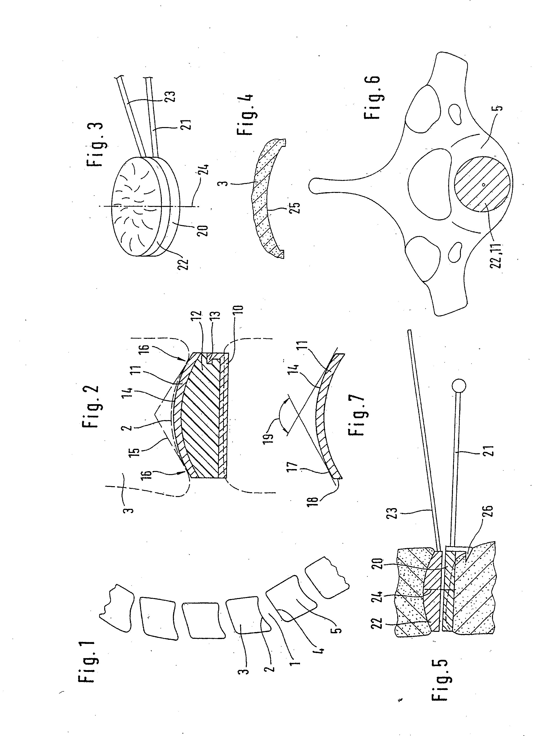
[0028] A side-on X-ray image of the cervical spine shows the contours of the vertebral bodies as illustrated in FIG. 1. It is clear from this that the intervertebral spaces 1 in sagittal section are delimited at the top by a concave bottom surface 2 of the upper vertebral body 3 and at the bottom by an approximately flat top surface 4 of the lower vertebral body 5.

[0029] From this, the invention derives the general rule that an intervertebral prosthesis should be convex at the top and made flat at the bottom.

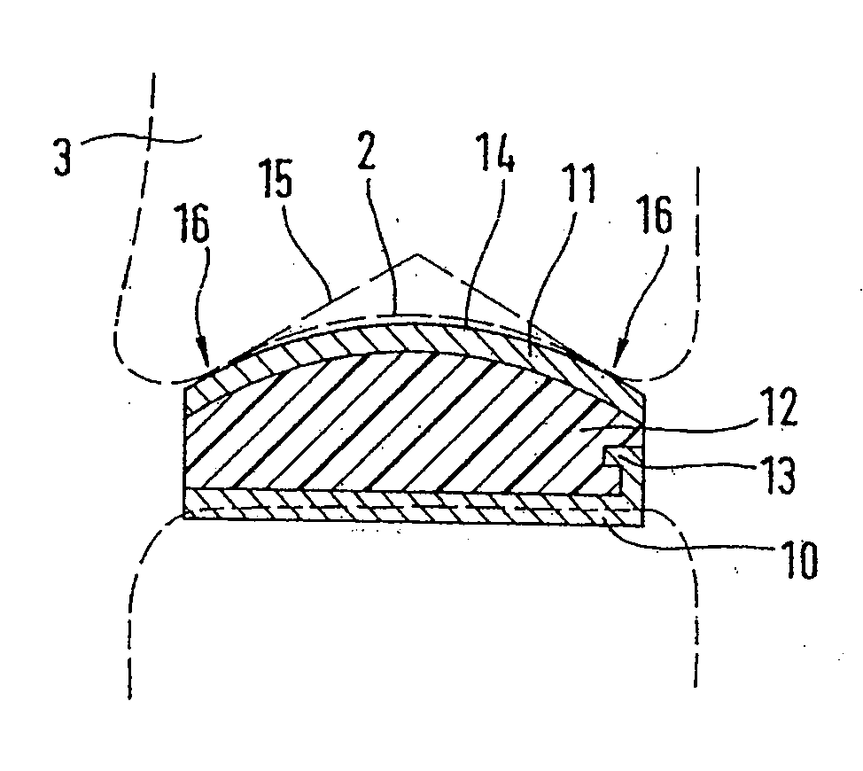
[0030] The illustrative embodiment shown in FIG. 2 consists of a lower cover plate 10, an upper cover plate 11, and a prosthesis core 12. The cover plate 10 has a substantially flat surface extent and has, at the margin, retainer profiles 13 for retaining the prosthesis core 12. In sagittal section, the upper cover plate 11 is delimited by an outer surface contoured as a convex arc of a circle. In a known manner, the inner surface forms, together with the associated surface of...


PUM

PropertyMeasurementUnit
apex angleaaaaaaaaaa
angleaaaaaaaaaa
angleaaaaaaaaaa

Abstract

A cervical prosthesis includes a lower cover plate which is configured to be connected to a lower vertebral body, an upper cover plate which is configured to be connected to an upper vertebral body, and a prosthesis core which forms a hinged connection between the upper cover plate and lower cover plate. The bottom surface of the lower cover plate is substantially flat. The top surface of the upper cover plate is convex at least in sagittal section.

Description

REFERENCE TO RELATED APPLICATIONS [0001] This application is a continuation-in-part of Ser. No. 10 / 768,713, filed Feb. 2, 2004, now abandoned, the disclosure of which is incorporated herein by reference.FIELD OF THE INVENTION [0002] The invention relates to a cervical prosthesis consisting of a lower cover plate, an upper cover plate, and a prosthesis core which forms a hinged connection between the upper cover plate and lower cover plate. The lower cover plate is to be connected to a lower vertebral body, and the upper cover plate is to be connected to an upper vertebral body. BACKGROUND OF THE INVENTION [0003] It is known for the outer surfaces of the prosthesis cover plates to be designed flat (EP-A1-344508) or with a convex bulge (EP-A-1166725; WO-A-0211650). To ensure that these surfaces can cooperate properly with the vertebral body surfaces delimiting the intervertebral space, said vertebral body surfaces are milled to obtain the correct shape (WO-A-03075774; U.S. Pat. No. 6,...

Claims


Application Information

Patent Timeline
Patent Type & Authority Applications(United States)
IPC IPC(8): A61F2/44A61B17/16A61F2/00A61F2/30
CPCA61B17/1624A61B17/1659A61B17/1671A61F2/4425A61F2002/30113A61F2002/30125A61F2310/00796A61F2002/30841A61F2002/443A61F2230/0006A61F2230/0008A61F2310/00011A61F2002/30649
Inventor LINK, HELMUT D.KELLER, ARNOLDMCAFEE, PAUL C.
Owner CERVITECH INC
Why Eureka
Try Eureka