
Planting device and planting structure for plants

a planting device and plant technology, applied in the field of plant planting devices and planting structures, can solve the problems of increasing the cost of the device or structure, and heavy concrete layer, etc., and achieves the effects of light weight, simple structure, and small number of components

Inactive Publication Date: 2008-02-14
TAJIMA RYOKKA
View PDF14 Cites 14 Cited by
  • Summary
  • Abstract
  • Description
  • Claims
  • Application Information

AI Technical Summary

Benefits of technology

[0024]Further, in any planting device for plants described above, the ribs may be provided on the bottom of the body portion for preventing the movement of soil and reinforcing the body portion used as a cabinet.
[0027]Further, in any planting device for plants described above, a partition plate may be provided on the bottom of the body portion for preventing the movement of soil.
[0036]The following effects can be obtained by the above constitution of the present invention.
[0037](a) Due to being simple in structure, small in number of components and light in weight, the device or the structure of the present invention can be available at a low cost and increase the construction efficiency.
[0038](b) Due to the fact that a scaffold is provided, various types of maintenance work can be done easily. For example, watering the plants over the surface of soil at each of the devices is not necessary but a uniform watering can be easily done over the soil of all the devices arrayed continuously. Such watering can be done simply by allowing water to pass through a water supply pipe, thereby saving the time.
[0039](c) Where a construction surface on which greening is carried out is gradient, the devices can be easily formed continuously to attain a high efficiency particularly in terms of watering. In other words, in a conventional technology, spraying water must be done at each of the devices even at such a place. However, in the present invention, if watering is done with the device at upward step side, the surplus water continuously flow down to the device at downward step side, thereby providing a proper watering all over the area.

Problems solved by technology

However, in order to attain water retainability and water drainability enough for plants, a relatively large quantity of sediment must be introduced in a waterproof layer and the concrete layer is also considerably heavy.
The combined weight of these two layers affects a building, which is a problem.
However, it still has several problems which need to be improved.
Namely, the conventional device is complicated in structure and larger in the number of components, thereby raising costs of the device or structure and resulting in poor installation efficiency.
Further, this type of conventional device needs various kinds of maintenance work and such work is extremely difficult due to the absence of a scaffold.
For example, watering must be done over the surface of the soil of each of the devices and a uniform spraying water all over the entire soil surface of the device is difficult particularly due to the absence of a scaffold, thereby complicating the work to take a longer time.
Also, in a conventional technology, where a construction surface on which greening is carried out is gradient, the device cannot be formed continuously in a satisfactory manner causing problems in watering in particular.
To be more specific, at this type of place, watering must be done at each device, which is much more complicated and difficult due to the gradient comparing to the flat place.
However, in this technology, fixing the device is complicated to increase the installation costs and also need a longer time in the installation, which is a problem.
However, in the above-described planting device, a drain plate (water retainig / supply / draining means) and a truncated cone-shaped hollow body used as the fixing means are formed integrally and made complicated in shape and larger in size as a whole.
Therefore, where resin is used to form a drain panel, it is not easy to manufacture a mold, thereby increasing costs.
Further, it is complicated and requires some work to store and transport products.
There is, however, a difficulty in aligning the one member with the other, resulting in poor work efficiency, which is a problem.
Such necessity is not always met and this poses another problem.

Method used


Image

  • Planting device and planting structure for plants
  • Planting device and planting structure for plants
  • Planting device and planting structure for plants

Examples


Embodiment Construction

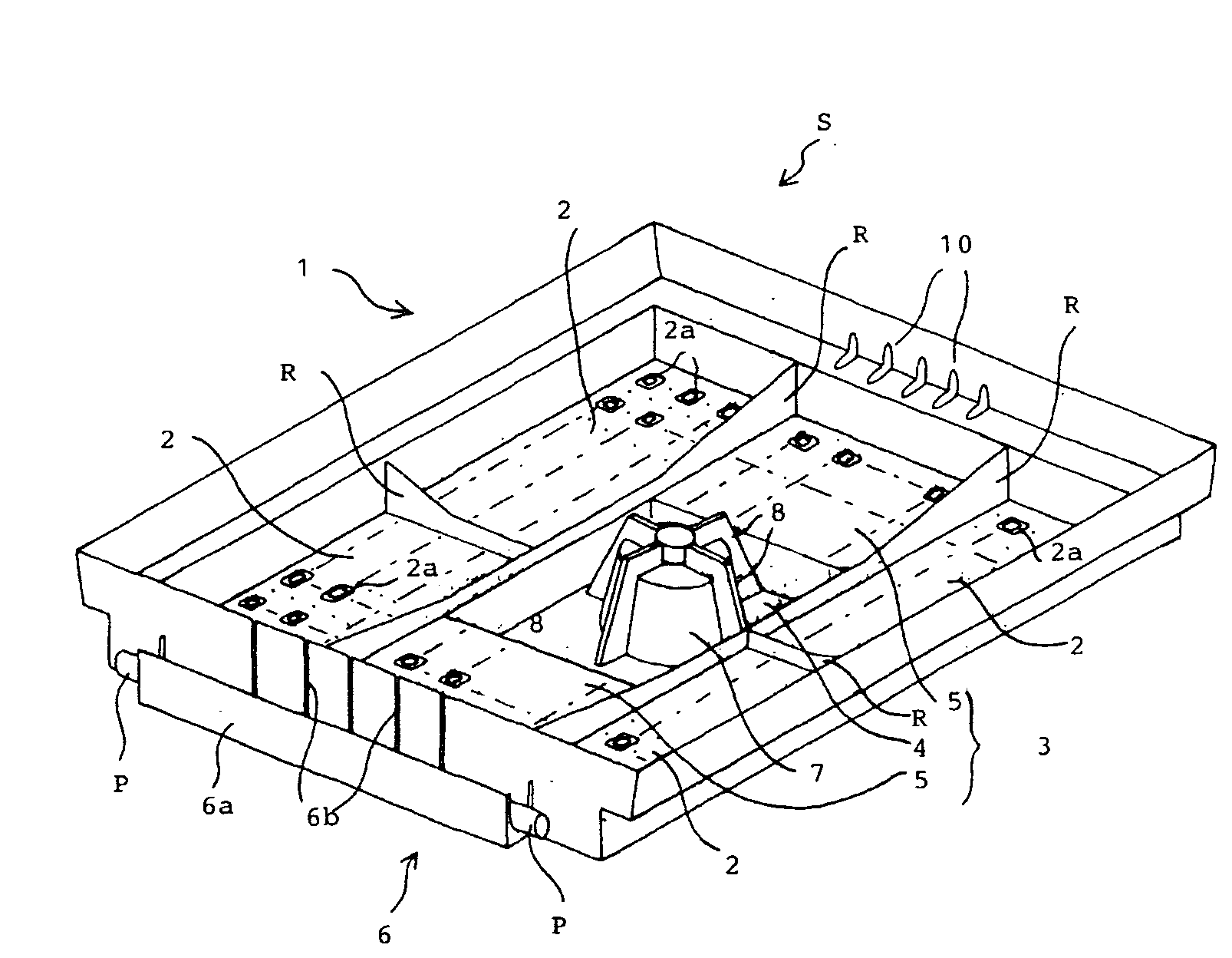
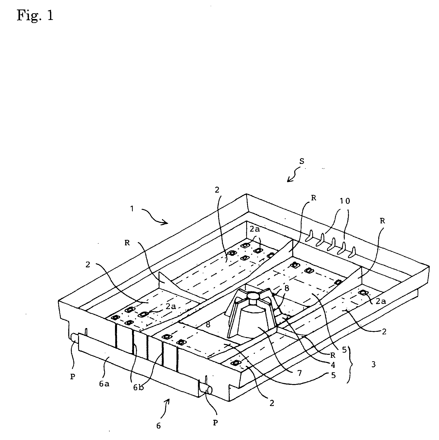
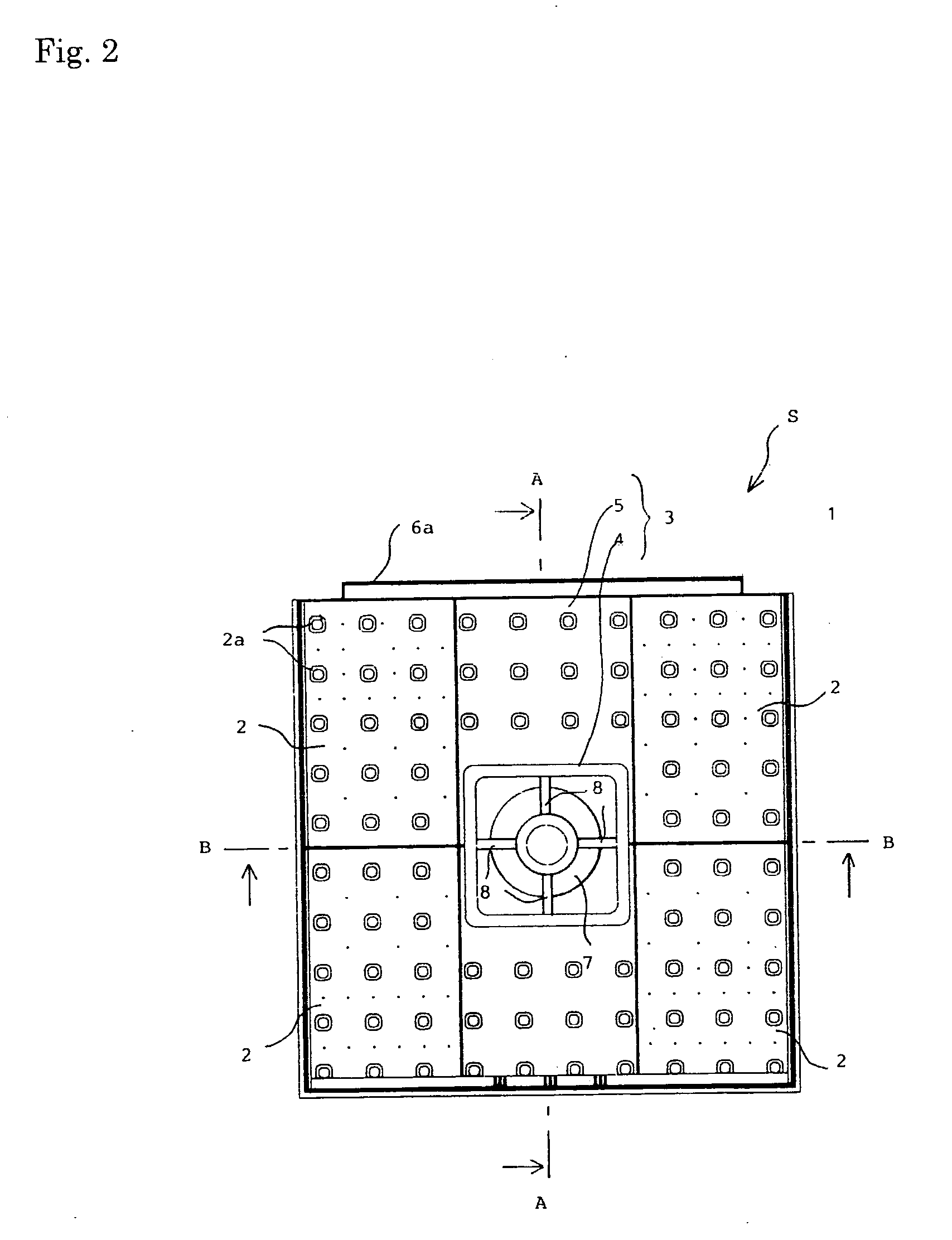
[0046]According to the present invention, a planting device is provided with a body portion having a first fixing means and a second fixing means firmely fixed to a mounting surface of the body portion and linked to the first fixing means, the body portion is provided at the bottom with a water draining means, a water retaining means and the first fixing means, furthermore, the body portion is also provided at a side wall with a water receiving means, soil is filled into a surrounding space enclosed with the side walls, a water supply pipe is erected at the water receiving means, thereby supplying water to the water retaining means formed at the bottom of the body portion. Soil is filled into the body portion to plant desired plants (or a desired plant) and to cultivate thereon.

[0047]The body portion is constituted with a rectangular plastic cabinet, and a recessed part for reinforcement of the strength is formed at the bottom so that the thickness of the plastic is reduced to be li...


PUM


Abstract

A planting device which is simple in structure, small in number of components, light in weight, easy to conduct various types of maintenance work, low in material cost, high in construction efficiency, easy to continuously arrange when greening is carried out at a gradient surface, and in particular, high in work efficiency in terms of watering as well as a planting structure in which the planting device is used.The above problem is solved by providing a planting device for plants to be formed mainly on a rooftop or a roof of a building and the like, the planting device for plants comprising a body portion provided with a first fixing means and a second fixing means firmely fixed to a mounting surface of the body portion and linked to the first fixing means, wherein the body portion is provided at the bottom with a water draining means, a water retaining means and the first fixing means and also provided at a side wall with a water receiving means, soil is filled into a surrounding space enclosed with the side walls and desired plants (or a desired plant) are planted on the soil as well as a planting structure in which the planting device is used.

Description

BACKGROUND OF THE INVENTION[0001]1. Field of the Invention[0002]The present invention relates to a planting device for plants and a planting structure in which the device is used.[0003]The present invention relates to a device for cultivating garden trees, flowering plants and other plants easily. In particular, the present invention relates to a planting device mounted for growing plants on a rooftop or a roof of a building and also to a water supplying and draining board for loading soil in this planting device.[0004]2. Description of the Related Art[0005]In recent years, a growing number of attempts have been made for planting plants on rooftops of buildings and in other spaces on a large scale to green inorganic spaces in an urban area.[0006]For this purpose, in most cases, a holddown concrete layer is formed on a waterproof layer on a slab surface of building and the like, on which a gravel layer composed of sand, gravel and the like as well as a soil dressing layer are alterna...

Claims


Application Information

Patent Timeline
IPC IPC(8): A01G9/02
CPCA01G9/00A01G1/007Y02B80/32Y02A30/254A01G9/033
Inventor TAJIMA, KUNIOGOTOU, YOSHIAKI
Owner TAJIMA RYOKKA
Features
  • Generate Ideas
  • Intellectual Property
  • Life Sciences
  • Materials
  • Tech Scout
  • Unparalleled Data Quality
  • Higher Quality Content
  • 60% Fewer Hallucinations
Learn More