Reduced size bowl for display glass melting and delivery

a glass and bowl technology, applied in glass rolling equipment, glass tempering equipment, manufacturing tools, etc., can solve the problems of inacceptable use of glass sheets, slow recovery, stagnant glass formation, etc., to reduce manufacturing costs, reduce stagnant glass formation, and eliminate stagnant glass.

Inactive Publication Date: 2008-02-14
CORNING INC
View PDF2 Cites 18 Cited by
  • Summary
  • Abstract
  • Description
  • Claims
  • Application Information

AI Technical Summary

Benefits of technology

[0009]In yet another preferred embodiment, a method for forming sheet glass is provided that comprises providing a reservoir that stores molten glass therein, and providing an inlet tube that receives the molten glass from the reservoir, wherein the inlet pipe has a cross-sectional area orthogonal to a direction of flow of the molten glass in the glass pipe. The method also comprises providing a bowl that receives the molten glass from the inlet pipe, wherein the bowl has a cross-sectional area orthogonal to a direction of the flow of the molten glass through the bowl that is equal to or less than the cross-sectional area of the inlet pipe, thereby eliminating stagnation of the molten glass within the bowl. The method further comprises providing a trough that receives the molten glass from the bowl, and forming a glass sheet by flowing the molten glass from the trough and over a wedge-shaped sheet forming structure.
[0010]The present invention provides a method and related apparatus that reduces the formation of stagnant glass and resultant glass defects in the overall process of glass sheet manufacture. The present invention further results in reduced manufacturing costs by decreasing related scrap rates, may be economically implemented within existing manufacturing systems, and is particularly well adapted for the proposed use.

Problems solved by technology

One of the problems associated with the overflow process is the formation of stagnant glass within at least one of the associated steps of the manufacturing process.
As is known, stagnant glass formed during the process results in streak or cord defects in the ultimately formed glass sheet, thereby making the sheet unacceptable for the uses as noted above.
The cause of this slow recovery is in part caused by quiescent or stagnant zones of glass flow within the associated apparatus.
During unintended process transient, these stagnant zones slowly bleed glass of a previous material composition into the main process stream of the current batch of glass being processed, thereby effecting the overall composition of the glass and causing defects therein.
These defects eventually subside as the glass is processed, however, a significant amount of processed glass may be unsuitable for use, thereby increasing overall scrap rates.
Moreover, previous manufacturing systems have incorporated relatively large bowls therein, so as to provide sufficient thermal mixing of the molten glass, but which contributes to the formation of stagnant glass.
Therefore, an apparatus and related method is needed that reduces the formation of stagnant glass and resultant glass defects in the overall process of glass sheet manufacture.

Method used


Image

  • Reduced size bowl for display glass melting and delivery
  • Reduced size bowl for display glass melting and delivery
  • Reduced size bowl for display glass melting and delivery

Examples


Embodiment Construction

[0019]For purposes of description herein, the terms “upper,”“lower,”“right,”“left,”“rear,”“front,”“vertical,”“horizontal,” and derivatives thereof shall relate to the invention as oriented in FIG. 1. However, it is to be understood that the invention may assume various alternative orientations and step sequences, except where expressly specified to the contrary. It is also to be understood that the specific devices and processes illustrated in the attached drawings, and described in the following specification are exemplary embodiments of the inventive concepts defined in the appended claims. Hence, specific dimensions and other physical characteristics relating to the embodiments disclosed herein are not to be considered as limiting, unless the claims expressly state otherwise.

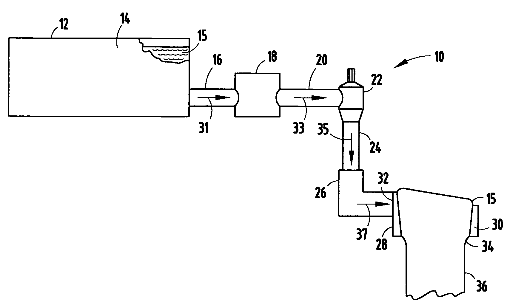
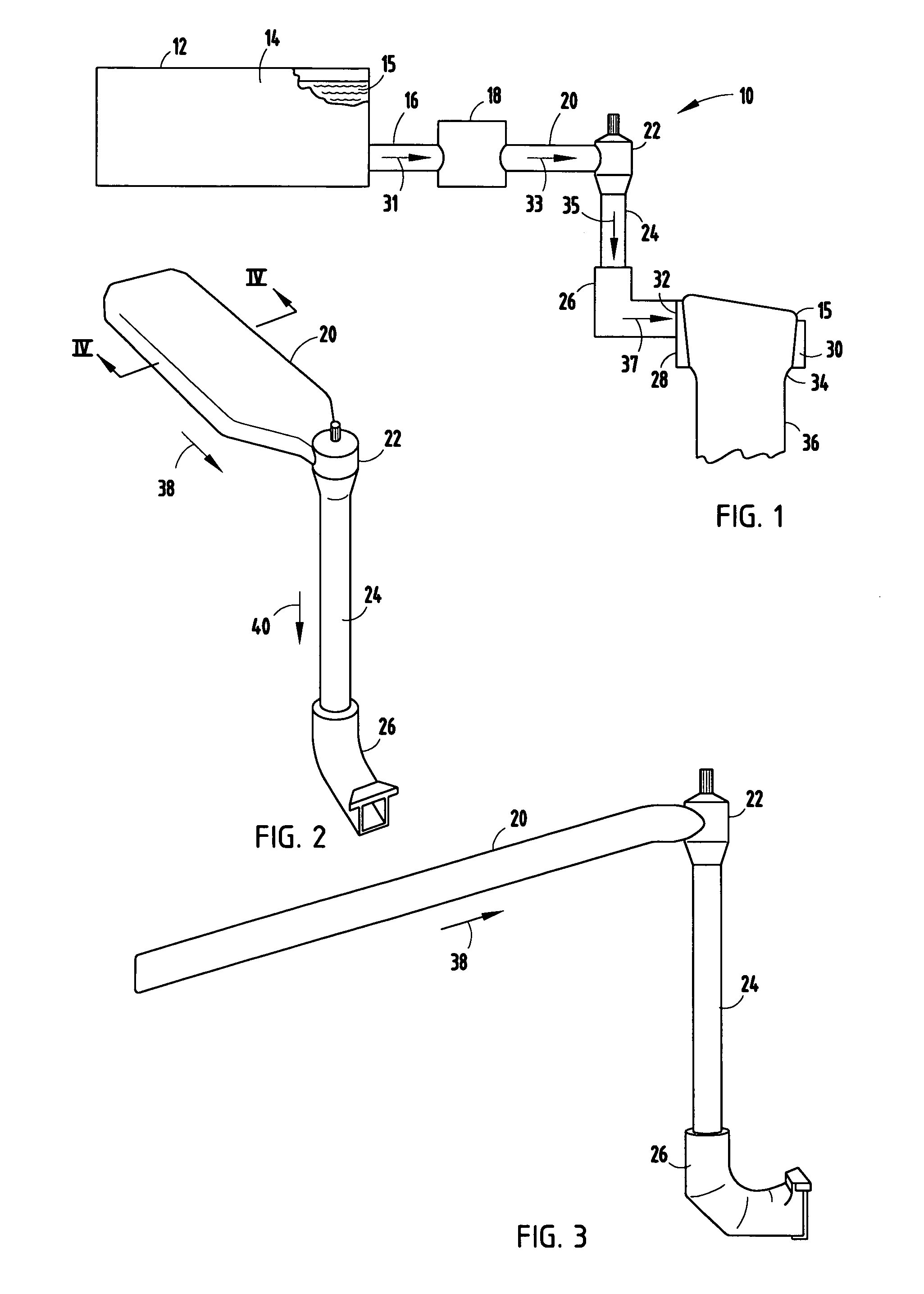
[0020]The reference numeral 10 (FIG. 1) generally designates a glass sheet manufacturing system incorporating the present invention. In the illustrated example, the glass sheet manufacturing system 10 include...


PUM

PropertyMeasurementUnit
lengthaaaaaaaaaa
cross-sectional areaaaaaaaaaaa
surface qualityaaaaaaaaaa

Abstract

The present invention provides an improved apparatus for forming sheet glass, wherein the apparatus includes a reservoir from which to provide molten glass, an inlet plate in fluid communication with the reservoir to receive the molten glass from the reservoir in a flow direction, the inlet pipe having a cross-sectional area orthogonal to the fluid direction, and a trough in fluid communication with the inlet pipe to receive the molten glass and that is operably coupled to a wedge-shaped sheet forming structure to form the molten glass into a glass sheet. The improvement comprises a bowl that provides fluid communication between the inlet pipe and the trough, the bowl having a cross-sectional area orthogonal to a fluid direction at the molten through the bowl that is equal to or less than the cross-sectional area of the inlet pipe, thereby preventing stagnation of the molten glass within the bowl. Another embodiment of the present invention is a method that utilizes the inventive apparatus to form glass sheet.

Description

BACKGROUND OF THE INVENTION[0001]1. Field of the Invention[0002]The present invention relates to the manufacture of glass sheet, and more particularly, to an improved process for the manufacture of glass sheet that eliminates stagnation of molten glass within an overflow-type process.[0003]2. Description of Related Art[0004]Glass used for semiconductor powered display applications, and particularly for TFT-LCD display devices and OLED display devices that are widely used for displays within PDAs, computer displays and the like, must provide a high surface quality to allow the successful application of semiconductor-type material. Sheet glass as manufactured utilizing the apparatus disclosed in U.S. Pat. No. 3,338,696, entitled SHEET FORMING APPARATUS, makes the highest quality glass as formed that does not require post-formation processing. This patent specifically discloses a manufacturing process typically referred to as “the overflow process,” that is particularly advantageous as...

Claims


Application Information

Patent Timeline
Patent Type & Authority Applications(United States)
IPC IPC(8): C03B13/00C03B5/26
CPCC03B17/064C03B7/02Y02P40/57C03B17/06
Inventor BERGMAN, RICHARDFRALEY, RAYMOND EUGENEXUN, MAY YAMMEI
Owner CORNING INC
Why Eureka
Try Eureka