Monitoring system for valve device
a valve device and monitoring system technology, applied in the direction of mechanical measuring arrangements, instruments, mechanical means, etc., can solve the problems of inability to measure small changes in thrust and torque, inability to compensate sufficiently for gauge sensitivity, and inability to achieve sufficiently accurate measuremen
- Summary
- Abstract
- Description
- Claims
- Application Information
AI Technical Summary
Benefits of technology
Problems solved by technology
Method used
Image

Examples
first embodiment
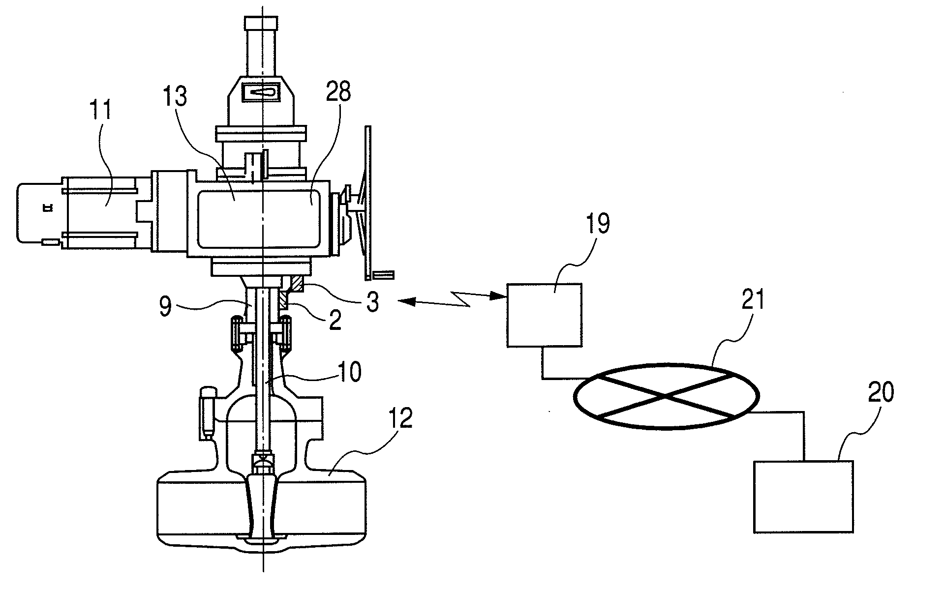
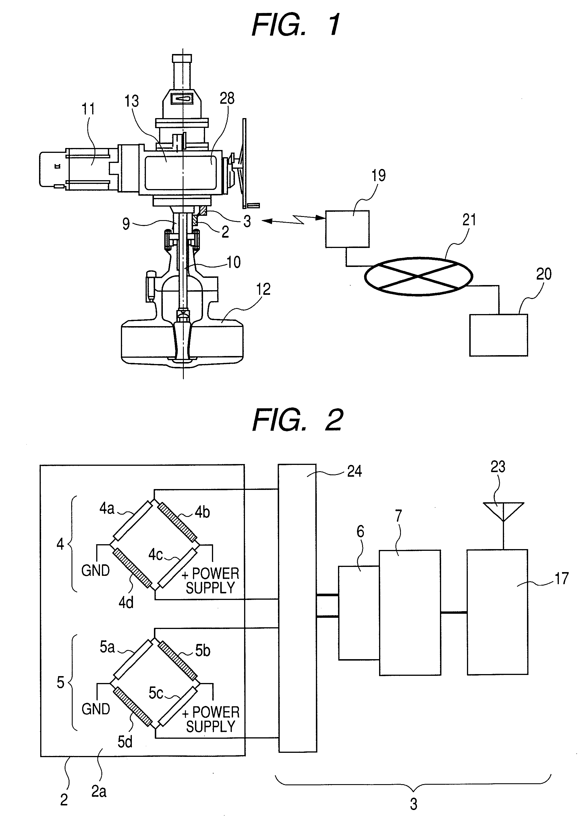
[0056] A first embodiment of the present invention will be described with reference to FIGS. 1 to 4. FIG. 1 shows a schematic illustration of major portions of a monitoring system for valve device according to a first embodiment. FIG. 2 is a block diagram showing the connections of an electric circuit located around the valve device in a first embodiment.
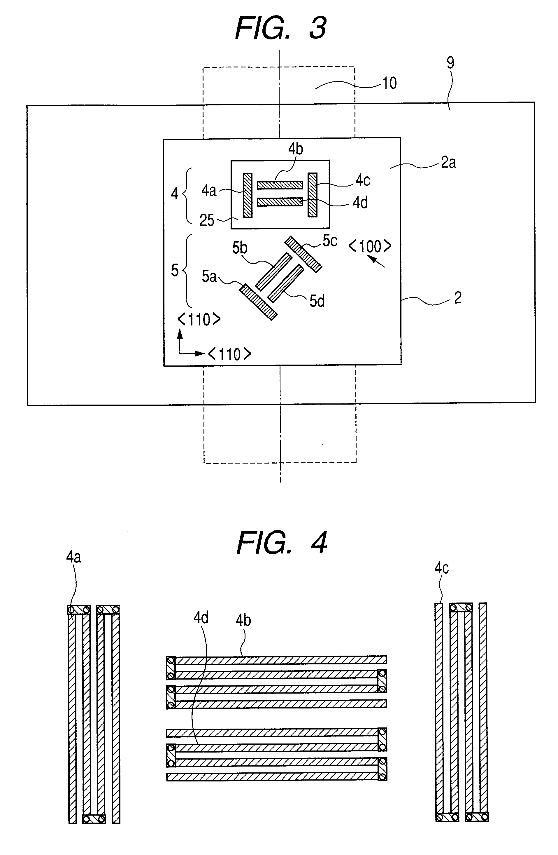
[0057] As shown in FIGS. 1 and 2, a semiconductor substrate 2 is disposed on the surface of a valve yoke 9. An output from the Wheatstone bridged circuits 4 and 5 which function as a strain sensing portion located in the semiconductor substrate 2 is lead to a controlling and transmitting unit 3. Subsequently, the output is digitalized by an A / D converter 6 located in the controlling and transmitting unit 3 via an amplifier 24 and is computed by a controlling and processing device 7, such as CPU or MPU. After that, the processed data is transmitted by a communication module 17. The data is received by a communication module and is c...
second embodiment
[0074] A second embodiment of the present invention will be described with reference to FIG. 2 and FIGS. 5 to 12. FIG. 5 is a schematic illustration of a monitoring system for valve device in a second embodiment. As shown in FIGS. 2 and 5, in this embodiment, a semiconductor substrate 2 is mounted to the valve stem 10, and a controlling and transmitting unit 3 also mounted to the valve stem 10 digitalizes data and transmits it. An output from the Wheatstone bridged circuits 4 and 5 which function as a strain sensing portion located in the semiconductor substrate 2 is lead to the controlling and transmitting unit 3. Subsequently, the output data is digitalized by an A / D converter 6 located in the controlling and transmitting unit 3 via an amplifier 24 and is computed by a controlling and processing device 7, such as CPU or MPU. After that, the computed data is transmitted by a communication module 17. The data is received by a communication module and is converted by an IP conversion...
third embodiment
[0091] A third embodiment of the present invention shows an example in which a semiconductor substrate 2 is mounted to an elastic body 28 of a torque switch in the valve device. FIG. 13 is a schematic installation around a valve drive gear of a monitoring system for valve device in a third embodiment of the present invention; and FIG. 14 is a schematic installation of a monitoring system for valve device in a third embodiment of the present invention. As shown in FIGS. 13 and 14, a driving force of a motor 11 is transmitted to the valve stem 10 via a power shaft 30, a gear 26, a gear 26′, a drive shaft 27, a worm gear 29, and a gear 26″ (a worm wheel). An elastic body 28 is disposed at the end portion of the drive shaft 27 so that the elastic body 28 elastically receives thrust according to load resistance of the worm gear 29. By utilizing the phenomenon that the drive shaft 27 moves right and left according to thrust that reflects load resistance, a torque switch 16 is provided whi...
PUM
 Abstract
Description
Claims
Application Information
 - Generate Ideas
- Intellectual Property
- Life Sciences
- Materials
- Tech Scout
- Unparalleled Data Quality
- Higher Quality Content
- 60% Fewer Hallucinations
Browse by: Latest US Patents, China's latest patents, Technical Efficacy Thesaurus, Application Domain, Technology Topic, Popular Technical Reports.
© 2025 PatSnap. All rights reserved.Legal|Privacy policy|Modern Slavery Act Transparency Statement|Sitemap|About US| Contact US: help@patsnap.com