Downhole Drill Bit

a drill bit and drill bit technology, applied in drill bits, earthwork drilling and mining, construction, etc., can solve the problems of reducing or eliminating the efficacy of cutting elements, reducing or eliminating the effect of cutting elements, and often subjecting cutting elements to intense forces

Active Publication Date: 2008-02-14
SCHLUMBERGER TECH CORP
View PDF99 Cites 81 Cited by
  • Summary
  • Abstract
  • Description
  • Claims
  • Application Information

AI Technical Summary

Problems solved by technology

Such cutting elements are often subjected to intense forces, torques, vibration, high temperatures and temperature differentials during operation.
As a result, stresses within the structure may begin to form.
Drag bits for example may exhibit stresses aggravated by drilling anomalies during well boring operations such as bit whirl or bounce often resulting in spalling, delamination or fracture of the superhard abrasive layer or the substrate thereby reducing or eliminating the cutting elements efficacy and decreasing overall drill bit wear life.
Damage typically found in drag bits may be a result of shear failures, although non-shear modes of failure are not uncommon.
The interface between the superhard material layer and substrate is particularly susceptible to non-shear failure modes due to inherent residual stresses.

Method used


Image

  • Downhole Drill Bit
  • Downhole Drill Bit
  • Downhole Drill Bit

Examples


Embodiment Construction

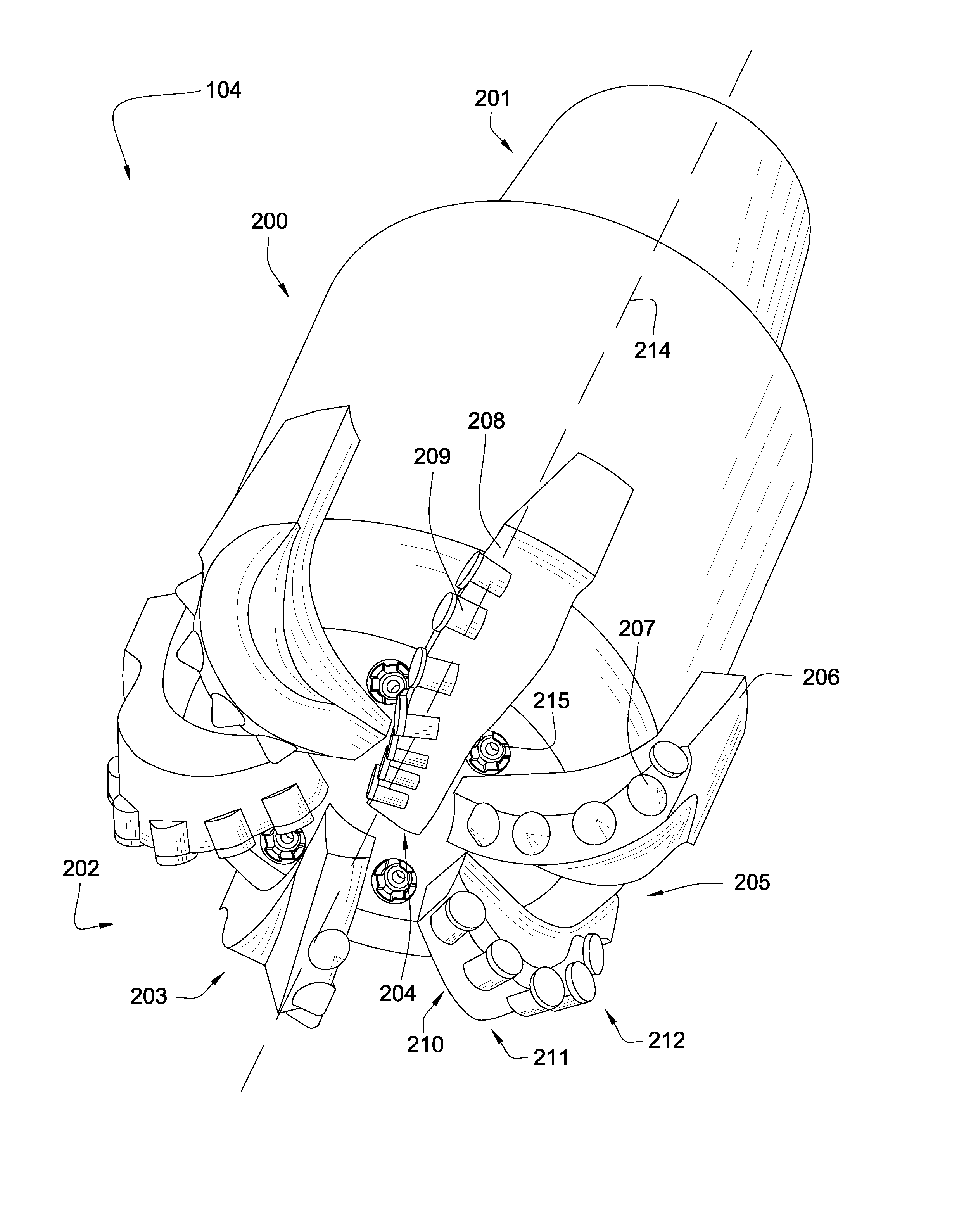
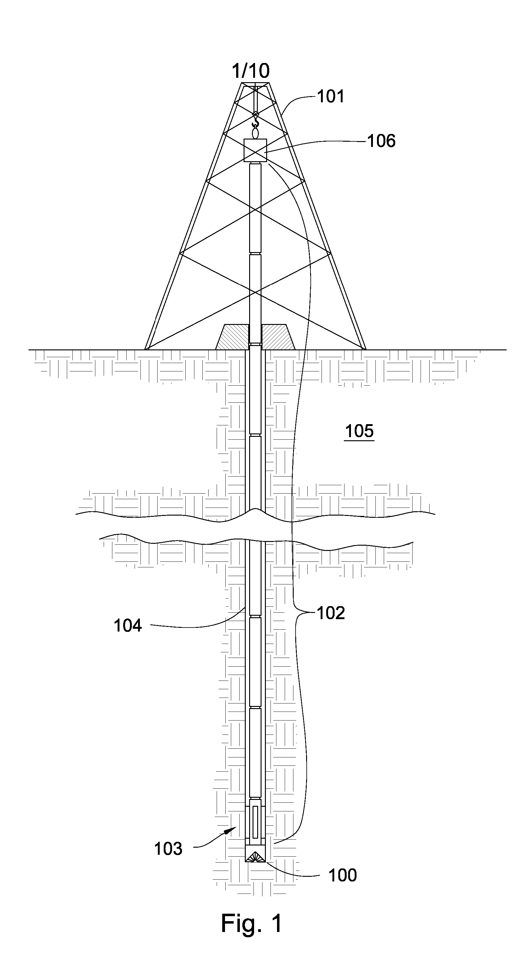
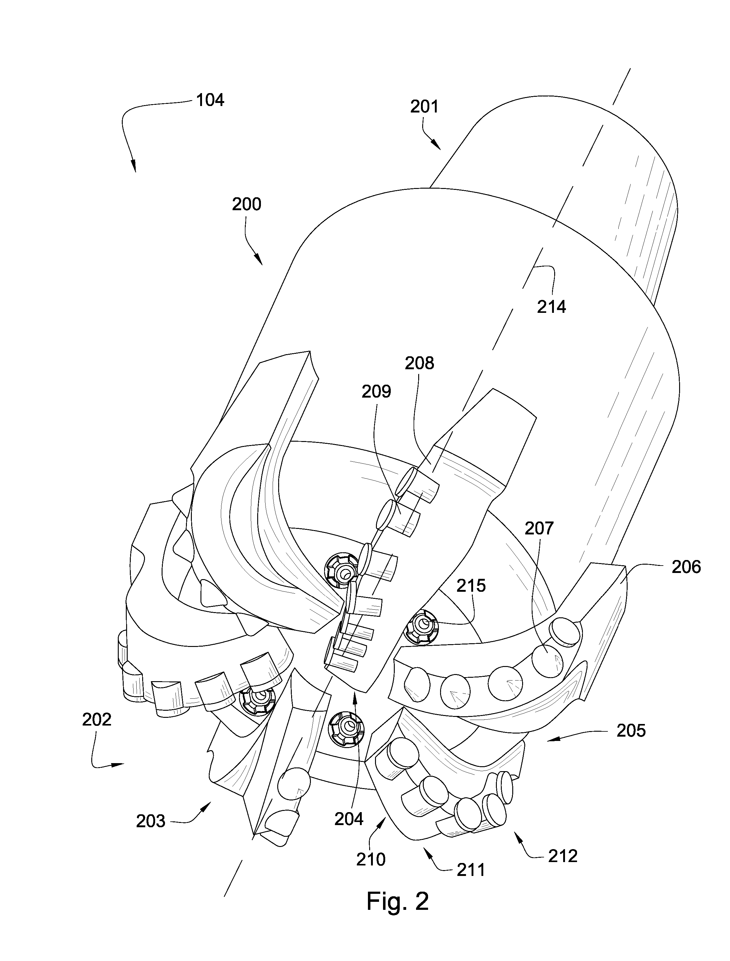
[0026]FIG. 1 is a perspective diagram of an embodiment of a drill string 100 suspended by a derrick 101. A bottom-hole assembly 102 is located at the bottom of a wellbore 103 and comprises a drill bit 104. As the drill bit 104 rotates downhole the drill string 100 advances farter into the earth. The drill string 100 may penetrate soft or hard subterranean formations 105. The drill bit 104 may break up the formations 105 by cutting and / or chipping the formation 105 during a downhole drilling operation. The bottom hole assembly 102 and / or downhole components may comprise data acquisition devices which may gather data. The data may be sent to the surface via a transmission system to a data swivel 106. the data swivel 106 may send the data to the surface equipment. Further, the surface equipment may send data and / or power to downhole tools and / or the bottom-hole assembly 102. U.S. Pat. No. 6,670,880 which is herein incorporated by reference for all that it contains, discloses a telemetr...


PUM


Abstract

In one aspect of the present invention, a drill bit has a body intermediate a shank and a working face. The working face has a plurality of blades converging towards a center of the working face and diverging towards a gauge of the working face. A first blade has at least one pointed cutting element with a carbide substrate bonded to a diamond working end with a pointed geometry at a non-planar interface and a second blade has at least one shear cutting element with a carbide substrate bonded to a diamond working end with a flat geometry.

Description

CROSS REFERENCE TO RELATED APPLICATION [0001] This application is a continuation-in-part of U.S. patent application Ser. No. 11 / 829,577, which was filed on Jul. 27, 2007. U.S. patent application Ser. No. 1 / 829,577 is a continuation-in-part of U.S. patent application Ser. No. 11 / 766,975 and was filed on Jun. 22, 2007. This application is also a continuation-in-part of U.S. patent application Ser. No. 11 / 774,227 which was filed on Jul. 6, 2007. U.S. patent application Ser. No. 11 / 774,227 is a continuation-in-part of U.S. patent application Ser. No. 11 / 773,271 which was filed on Jul. 3, 2007. U.S. patent application Ser. No. 11 / 773,271 is a continuation-in-part of U.S. patent application Ser. No. 11 / 766,903 filed on Jun. 22, 2007. U.S. patent application Ser. No. 11 / 766,903 is a continuation of U.S. patent application Ser. No. 11 / 766,865 filed on Jun. 22, 2007. U.S. patent application Ser. No. 11 / 766,865 is a continuation-in-part of U.S. patent application Ser. No. 11 / 742,304 which was...

Claims


Application Information

Patent Timeline
Patent Type & Authority Applications(United States)
IPC IPC(8): E21B10/42
CPCE21B10/43E21B10/54
Inventor HALLBAILEY, JOHNCROCKETT, RONALD B.
Owner SCHLUMBERGER TECH CORP
Why Eureka
Try Eureka