[0015] This invention relates to a method of decontaminating, purifying and / or sterilizing air that contains undesired products such as airborne pathogenic agents or microorganisms such as spores, bacteria, viruses, yeasts and moulds. The method can also be used to decontaminate a gas which contains non-living substances such as volatile organic compounds (VOC), fumes, organophosphates, etc. The method consists in damaging and braking up the contaminant molecular structure by oxidation, reduction and chemical bond rupture. Through this process the microorganisms or the contaminants are inactivated through structural damages to the cellular membrane and / or the nucleus membrane and / or to the DNA structure or by breaking the contaminant into simpler non-toxic molecular structures. This is accomplished by creating through the air to be treated, various electronic currents having a plurality of specific and controlled average kinetic energies matching or exceeding the desired chemical bonds to be affected and / or ruptured and / or oxidized in the contaminants. The air interaction with such various currents, under specific energies, sufficient intensities and exposition time is achieved by the use of sets of specially configured electrodes designed to produce and control the desired electronic kinetic energy and accomplished through several stages to decontaminate and / or sterilize the air or gas and to finally remove undesirable by-products that can be present so that it can be safely used directly or stored.
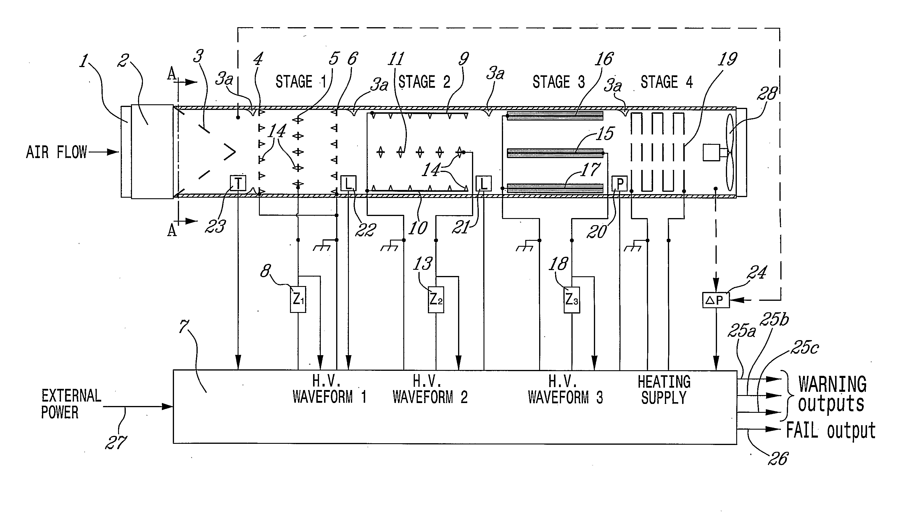
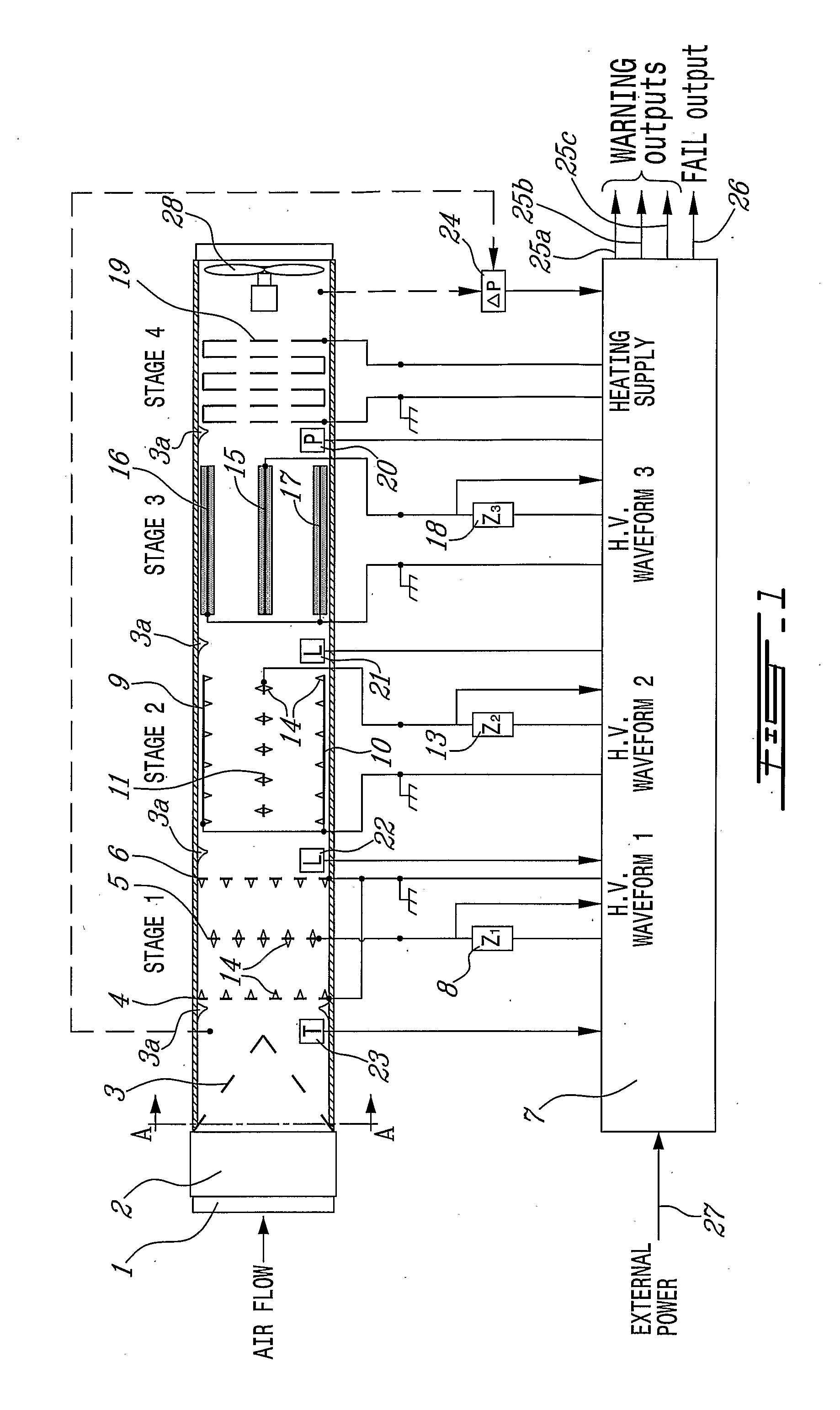
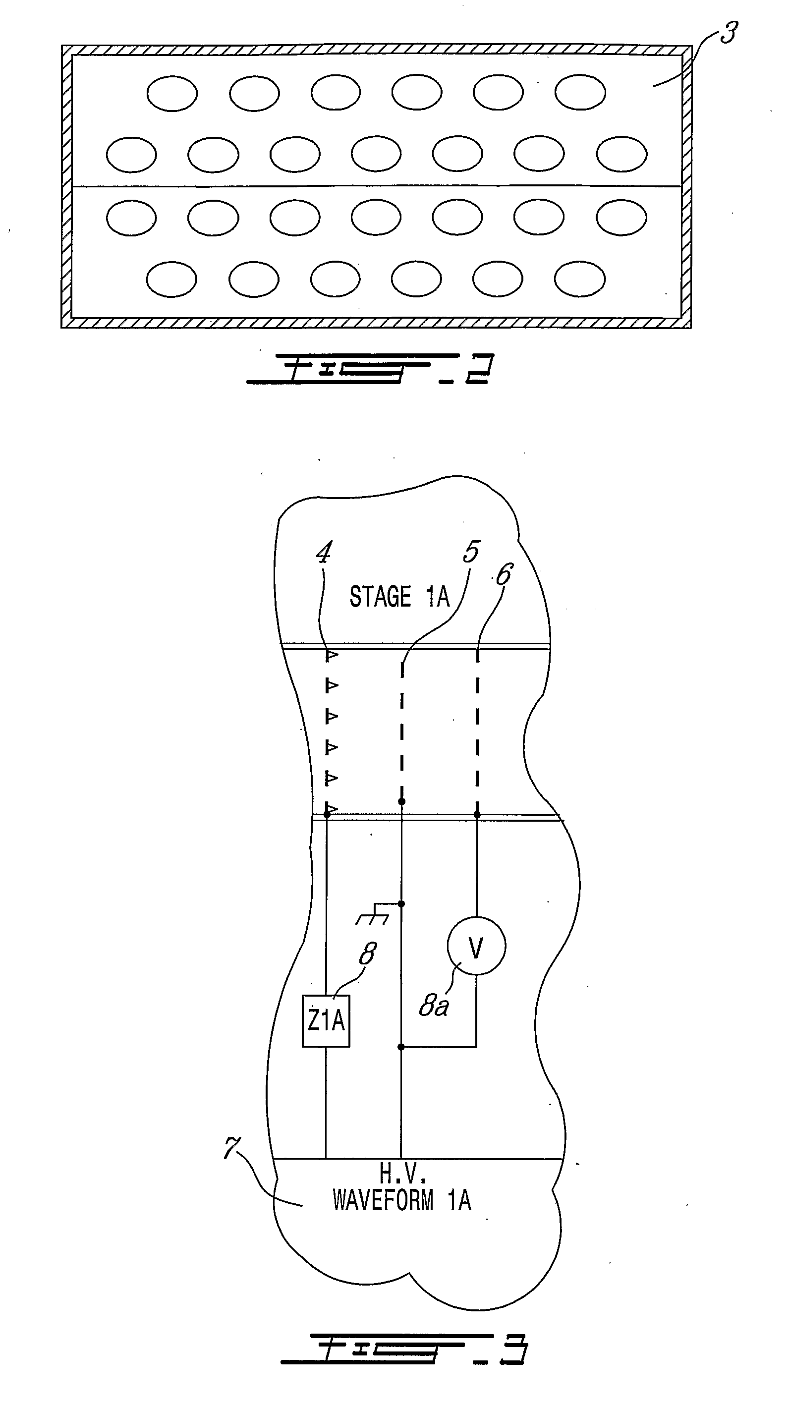
[0016] According to one broad aspect of the present invention, there is provided a multi-electrode system for decontaminating a gas containing contaminants flowing therein. The system comprises: a passageway for allowing the gas to flow from a first end to a second end of the passageway; at least one set of three electrodes having two outer electrodes electrically connected together forming a first terminal and one inner electrode placed between the two outer electrodes and forming a second terminal, wherein each set is placed within the passageway and in one of a perpendicular and a parallel orientation to the flow of gas and wherein the set is permeable to the gas flow when placed in a perpendicular orientation to the gas flow; a high voltage waveform source for supplying the first and second terminals and creating electrical fields between the outer electrodes and the inner electrode, wherein the electrical fields interacting with the gas to create an electronic current having a desired average energy level to at least match the energy level of the molecular bonds of the contaminants to be at least one of ruptured, and / or damaged and / or modified; and wherein the set has at least one of (a) at least one surface of the inner electrode and a corresponding exposed surface of the outer electrodes which are fitted with protuberances having a controlled geometry on the surface thereby controlling amplification factor of the electric field at extremities of the protuberances; and (b) a space between at least one outer electrode and the inner electrode which is at least partially filled with elements made from a dielectric material.
[0017] According to another broad aspect, there is provided a multi-electrode system for decontaminating a gas containing contaminants flowing therein. The system comprises: a passageway for allowing the gas to flow from a first end to a second end of the passageway; at least one set of two electrodes each having a terminal, wherein each set is placed within the passageway and in one of a perpendicular and a parallel orientation to the flow of gas and wherein the set is permeable to the gas flow when placed in a perpendicular orientation to the gas flow; a high voltage waveform source for supplying the terminals and creating an electrical field between the electrodes, wherein the electrical field interacts with the gas to create an electronic current having a desired average energy level to at least match the energy level of the molecular bonds of the contaminants to be at least one of ruptured, damaged and modified; and wherein the set has at least one of (a) an exposed surface of the electrodes is fitted with protuberances having a controlled geometry on the surface thereby controlling an amplification factor of the electric field at extremities of the protuberances; and (b) a space between the electrodes is at least partially filled with elements made from a dielectric material.
[0018] A system for decontaminating a gas is provided. The system comprises: a passageway containing at least one set of two or three electrodes. If the set contains three electrodes, it has two outer electrodes electrically connected together and one inner electrode. A high voltage waveform source for creating electrical fields between the electrodes, wherein the electrical fields interact with the gas to create an electronic current having a desired average energy level to at least match the energy level of the molecular bonds of the contaminants to be ruptured and wherein the set has either (a) at least one surface of the inner electrode and a corresponding exposed surface of the outer electrodes (in the case of a set with two electrodes, both exposed surfaces) are fitted with protuberances having a controlled geometry controlling an amplification factor of the electric field at extremities of the protuberances; or (b) a space between at least one outer electrode and the inner electrode (in the case of a set with two electrodes, a space between the electrodes) is at least partially filled with elements made from a dielectric material.
[0019] In the art, the term “sterilization” is used to mean the act of removing or inactivating (render non-living and non-self-replicating) all microorganisms from a medium, a typical acceptable level of contamination following a sterilization being 1 particle per 106 or 107. The term “decontamination” is used in the art to mean the removal or inactivating of most microorganisms from a medium, a typical acceptable level of contamination following a decontamination being 1 particle per 104 or 105. Therefore, in the present application, the term “decontamination” is intended to include a decontamination of the gas so effective that a sterilization occurs.
[0020] It will be readily understood that the concept of “air” is included in the meaning of the term “gas”. Indeed, “air” is understood to mean a colorless, odorless, tasteless, gaseous mixture, mainly nitrogen (approximately 78 percent) and oxygen (approximately 21 percent) with lesser amounts of argon, carbon dioxide, hydrogen, neon, helium, and other gases while “gas” is understood to mean any substance in the gaseous state. Therefore, “air” being in a gaseous state, it is a gas. In the present application, the term “gas” is intended to include air, as well as any other gases. The terms “air” and “gas” are used interchangeably.

