Light emitting device

a technology of light emitting device and sealing resin, which is applied in the direction of solid-state device, spectral modifier, lighting and heating apparatus, etc., can solve the problem of not being able to suppress the sealing resin in sufficient quantities, and achieve the effect of long service life and high reliability

Active Publication Date: 2008-02-14
NICHIA CORP
View PDF13 Cites 67 Cited by
  • Summary
  • Abstract
  • Description
  • Claims
  • Application Information

AI Technical Summary

Benefits of technology

[0030] The constitution of the present invention described above makes it possible to provide the light emitting device which has high reliability and long service li

Problems solved by technology

However, scatter by the granular particles added in the resin is not enough to supp

Method used


Image

  • Light emitting device
  • Light emitting device
  • Light emitting device

Examples


first embodiment

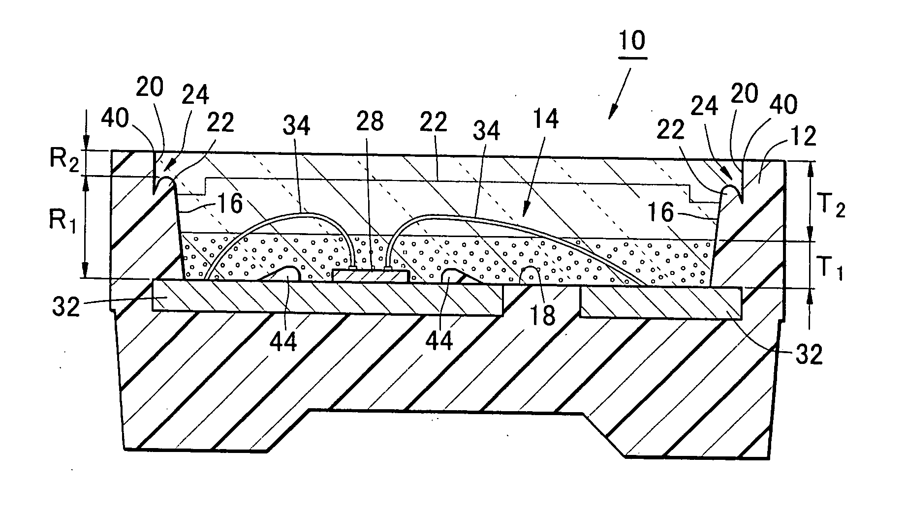
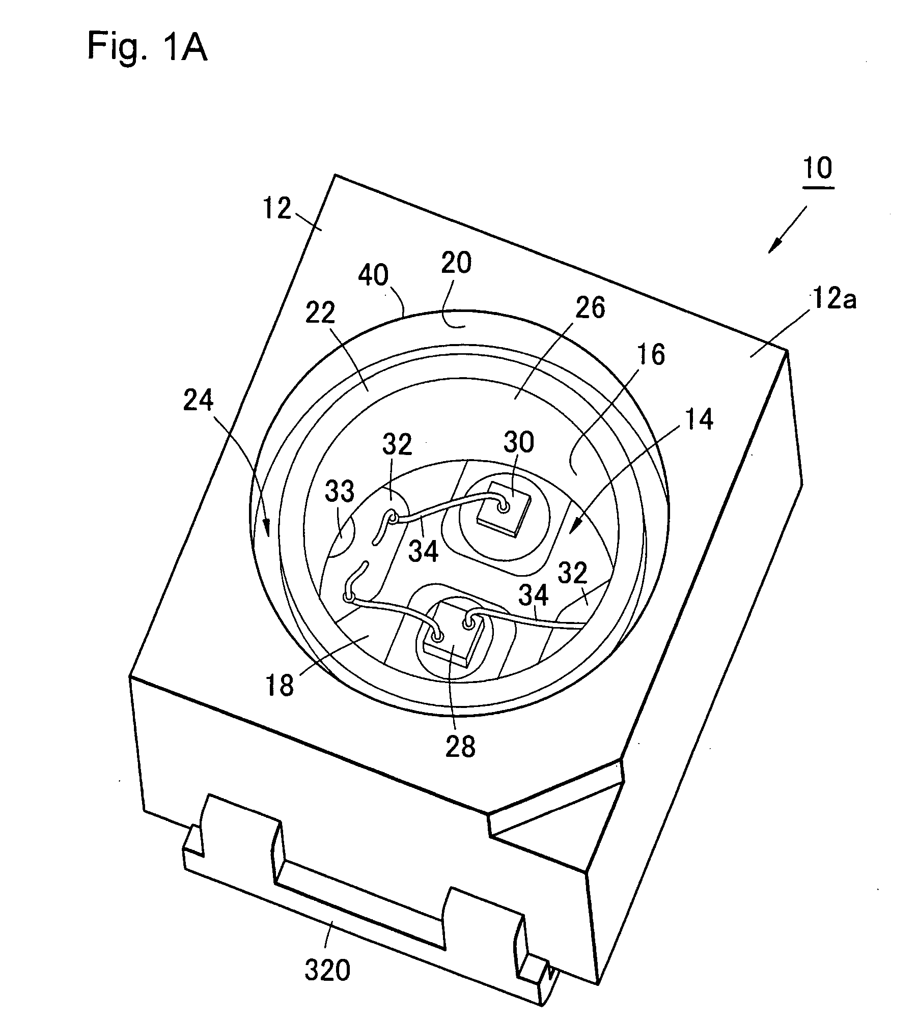
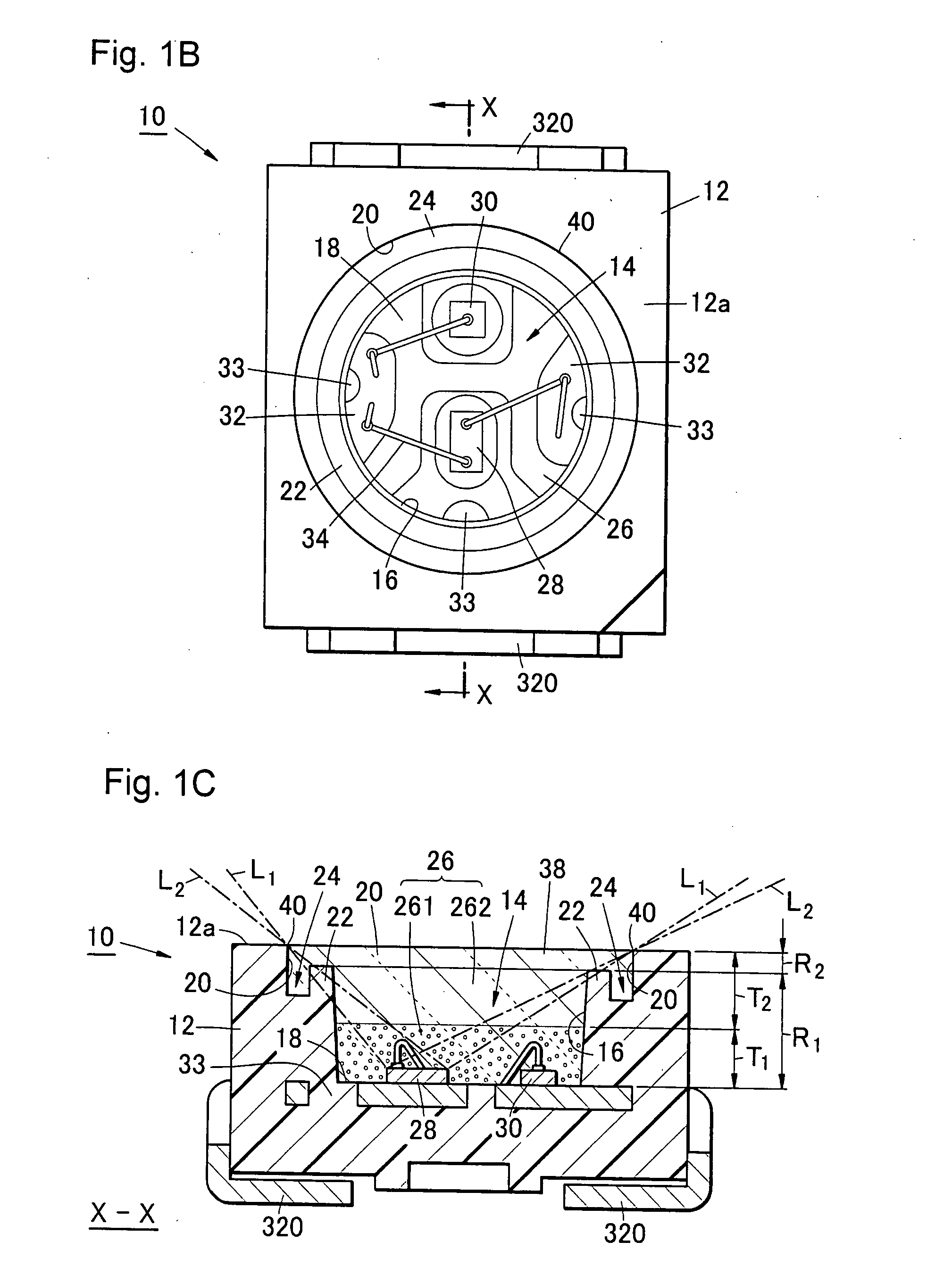
[0075] A light emitting device 10 of this embodiment shown in FIG. 1A through 1C comprises a housing 12 having a recess 14 with circular opening 38 and cross section of inverted trapezoid shape, and a plurality of lead electrodes 32 which are exposed on the bottom 18 of the recess 14. Disposed over the lead electrodes 32 are light emitting element 28 and a protective element 30 die-bonded thereon for electrically protecting the light emitting element 28, and are electrically connected with the lead electrodes 32 by means of electrically conductive wires 34. The light emitting element 28 is wire-bonded by means of the electrically conductive wires 34 so as to be electrically connected to the lead electrodes 32 which are exposed on the bottom 18 of the recess 14. Since the lead electrodes 32 penetrate through the housing 12 and are connected to external electrodes 320, electrical power can be supplied to the light emitting element 28 by applying a voltage to the external electrodes 32...

second embodiment

[0142] Second embodiment shown in FIG. 4 and FIG. 5 is the light emitting device 10 where a notch 42 is formed in a part of the recess 14 of the housing 12, so as to increase the area of the lead electrode 32 which is exposed. The protective element 30 is die-bonded onto the lead electrode 32 which is exposed through the notch 42. The light emitting device 10 of this embodiment is similar to that of the first embodiment, except for the notch 42 and the position of mounting the protective element 30.

[0143] When the notch 42 is formed as in this embodiment, a part of the light blocking section 22 is removed. As a result, the inner edge 20 of the opening of the recess 14 of the housing 12 is illuminated by the light incident directly from the light emitting element 28 via the notch 42.

[0144] However, providing the notch 42 makes it easier to mount the protective element 30 in the light emitting device which is made compact. Even when the space for mounting the semiconductor element i...

third embodiment

[0155] The light emitting device 10 of the third embodiment shown in FIG. 9A through FIG. 9D is a side-emitting type light emitting device suitable for the backlight of a thin liquid crystal panel, unlike the top-emitting type light emitting device described in the first and second embodiments. Accordingly, it has the housing 12 and the lead electrodes 32 which have different configurations, but is similar to the first and second embodiments with other respects.

[0156] The housing 12 of flat shape has the recess 14 opening in the light emitting surface 12a, and the lead electrodes 32 are partially exposed on the bottom 18 of the recess 14. Disposed over the lead electrodes 32 is the light emitting element 28 die-bonded thereon and electrically connected with the lead electrodes 32 by means of the electrically conductive wires 34. The grid 44 of two parallel ridges are formed between both sides of the position of die-bonding the light emitting element 28, so as to prevent the adhesiv...


PUM


Abstract

The present invention provides a light emitting device which has high reliability and long service life by suppressing the sealing resin from peeling off the inner edge of the opening of the recess of the housing. The light emitting device of the present invention comprises a light emitting element having a pair of electrodes, a housing having a recess for accommodating the light emitting element, a first lead electrode and a second lead electrode which are exposed on the bottom of the recess, electrically conductive members for electrically connecting the pair of electrodes of the light emitting element to the first lead electrode and to the second lead electrode respectively, a transparent sealing material which fills in the recess and granular additives contained in the sealing material, wherein the inner wall surface of the recess has a light blocking section that blocks light emitted by the light emitting device toward the inner edge of the opening of the recess, the quantity of the granular additives contained in the sealing material is controlled to such a level that enhances scattering of light in a first region located below the light blocking section and to such a level that suppresses scattering of light in a second region located above the light blocking section.

Description

BACKGROUND OF THE INVENTION [0001] 1. Field of the Invention [0002] The present invention relates to a light emitting device, and particularly to a light emitting device having high heat resistance and high durability. [0003] 2. Description of the Related Art [0004] Among light emitting devices that employ light emitting elements such as light emitting diode, a light emitting device having a housing which protects the to the light emitting element is known. The housing has a recess formed on the light emitting side thereof so that, after the light emitting element is mounted in the recess, the recess is filled with a transparent sealing material for the protection of the light emitting element from the environment. [0005] The housing is formed from an electrically insulating resin which is appropriate for electrically and mechanically protecting the light emitting element. For example, a nylon-based resin such as polyphthalamide or polyamide, a liquid crystal polymer, or an epoxy-ba...

Claims


Application Information

Patent Timeline
IPC IPC(8): F21V31/00F21V9/16H01L33/32H01L33/50H01L33/54H01L33/56H01L33/62
CPCH01L25/167H01L33/52H01L2924/01047H01L2924/01015H01L2924/3025H01L2924/19107H01L2224/4911H01L2224/48465H01L2224/48247H01L24/49H01L24/48H01L2224/45147H01L2224/45144H01L2224/45124H01L2933/0091H01L33/60H01L2924/00H01L2924/351H01L2224/45169H01L2924/12035H01L2924/12044H01L2924/12041H01L2224/05599H01L2224/85399H01L2924/181H01L2224/4809H01L2924/00014H01L24/45H01L2924/00012H01L2224/45015H01L2924/207
Inventor NII, IKUYAUKAWA, HIROAKIKASAE, NOBUHIDETAKAO, TOSHIMASA
Owner NICHIA CORP
Why Eureka
Try Eureka