Hydrophone Array Module

a technology of hydrophone array and module, which is applied in the direction of mechanical vibration separation, instruments, diagnostic recording/measuring, etc., can solve the problems of not being able to meet the needs of mass production, and being produced by skilled technicians in a very labor-intensive manner

Active Publication Date: 2008-02-14
QUALCOMM INC
View PDF4 Cites 18 Cited by
  • Summary
  • Abstract
  • Description
  • Claims
  • Application Information

AI Technical Summary

Problems solved by technology

The prior art devices, because of limited use and design, do not lend themselves well to mass production and are normally hand-made by skilled technicians in a very labor intensive manner.

Method used


Image

  • Hydrophone Array Module
  • Hydrophone Array Module
  • Hydrophone Array Module

Examples


Embodiment Construction

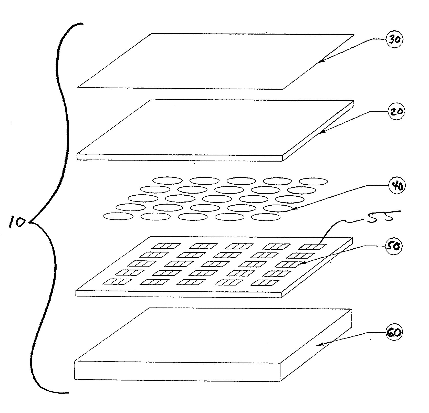
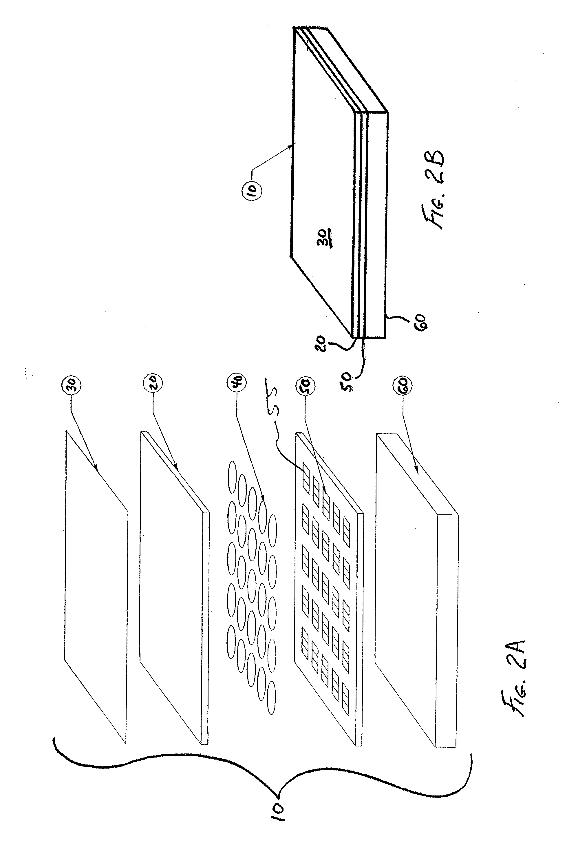
[0020]FIG. 2A is an exploded perspective view showing certain components of a hydrophone array 10 that is in keeping with the invention. FIG. 2B shows the hydrophone array 10 in assembled form. In this embodiment of the invention, an outer electrode 30 has been applied to one side of an electret film 20 and an array of inner conductive electrodes 40 have been applied to the other side of the electret film 20. The electret film 20 may include polyvinylidenefluoride (“PVDF”) polymer, or a copolymer of PVDF and trifluoroethylene (TrFE”). However, the invention is not limited to these materials, and the electret film 20 may be a polymer, ceramic, crystalline or polycrystalline material exhibiting electret properties.

[0021]Applying the electrodes 30, 40 may be accomplished by various means that may include masked and sputtered deposition or adhesive bonding. The outer electrode 30 and / or inner conductive electrodes 40 may also be created by masking and etching. The resulting assembly may...


PUM


Abstract

A hydrophone array includes hydrophones having an electret means and may have TFT FETs to generate current in response to received longitudinal wave signals. The arrangement may also be used to transmit longitudinal wave signals. Storage capacitors may be coupled to each TFT FET output to act as sample and hold means. Digital switches may allow the sample and hold circuit to both reset and measure the output of the hydrophone element. Data lines may be used to indicate the location of the received signal on the longitudinal wave detector sensor array.

Description

CROSS-REFERENCE TO RELATED APPLICATION[0001]This application claims the benefit of priority to U.S. provisional patent application Ser. No. 60 / 822,087, filed on Aug. 11, 2006.FIELD OF THE INVENTION[0002]The present invention relates to sensing and producing longitudinal waves. The present invention may be embodied as a flat panel longitudinal wave sensor array that employs an electret device.BACKGROUND OF THE INVENTION[0003]FIG. 1 depicts a prior art device having a single-element hydrophone 7. This device has a small finger-like electrode 4 (“finger electrode 4”) and a large area electrode 3 (“LA electrode 3”). Each of the electrodes is attached to a different side of an electret film 2 (“E film”). The molecules of the E film 2 are aligned so as to create a permanent electrostatic field. The two electrodes 3, 4 with the E film 2 between form a capacitor. When the distance between the electrodes 3, 4 changes, the voltage differential between the electrodes 3, 4 changes. The change i...

Claims


Application Information

Patent Timeline
Patent Type & Authority Applications(United States)
IPC IPC(8): H04R1/00H04B1/02
CPCG01H11/06A61B5/1172A61B8/08B06B1/0292G01N2291/02466G01N2291/044
Inventor SCHNEIDER, JOHN K.KITCHENS, JACK C.
Owner QUALCOMM INC
Why Eureka
Try Eureka