Optical Recording Medium

Inactive Publication Date: 2008-02-14
RICOH KK
View PDF8 Cites 8 Cited by
  • Summary
  • Abstract
  • Description
  • Claims
  • Application Information

AI Technical Summary

Benefits of technology

[0019] In addition, in multivalue recording, since the area of a mark is changed in a groove in which information is recorded, and reflected signal voltage reproduced from the changed mark area is divided at regular intervals to thereby read information, the number of errors of reproduced signals will be increased not to allow the information to be read when involved with not only loss of recorded marks and changes in mark length under high temperature and humidity conditions but also variations in reflectance due to changes in crystalline conditions between recorded marks. Further, for binary recording and multivalue recording, it is also requi

Problems solved by technology

In addition, in multivalue recording, since the area of a mark is changed in a groove in which information is recorded, and reflected signal voltage reproduced from the changed mark area is divided at regular intervals to thereby read information, the number of errors of reproduced sig

Method used


Image

  • Optical Recording Medium
  • Optical Recording Medium
  • Optical Recording Medium

Examples


example

[0103] Hereafter, the present invention will be described in detail referring to specific examples; however, the present invention is not limited to the disclosed examples.

examples 1 to 3

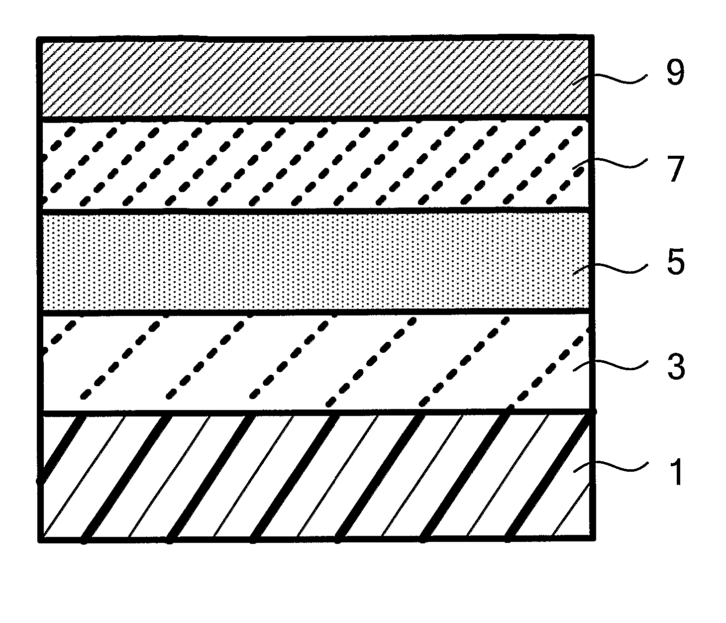
[0104] On a low birefringence polycarbonate substrate having a thickness of 0.6 mm and a guide groove provided thereon, the guide groove having a groove depth of 21 nm, a groove width of 0.30 μm, and a groove pitch of 0.45 μm (ST3000, manufactured by TEIJIN-Bayer Polytec Ltd.), a first protective layer made from ZnSSiO2 (70:30 mol %) and has a thickness of 41 nm, a recording layer made from materials of each compositions shown in the columns of Examples 1 to 3 in Table 1 and has a thickness of 14 nm, a second protective layer made from ZnSSiO2 (80:20 mol %) and has a thickness of 6 nm, an anti-sulfuration layer made from Nb2O5:SiO2=80:20 (mol %) and has a thickness of 4 nm, and a reflective layer made from Ag99.5Bi0.5 (atomic %) and having a thickness of 140 nm were disposed in this order by sputtering.

[0105] Next, on the reflective layer, a ultraviolet curable resin having a thickness of 7 μm (SD318, manufactured by DAINIPPON INK AND CHEMICALS, INC.) was used to form an environmen...

examples 25 to 36

[0127] On a low birefringence polycarbonate substrate having a thickness of 1.1 mm and a guide groove provided thereon, the guide groove having a groove depth of 22 nm, a groove width of 0.20 μm, and a groove pitch of 0.32 μm (ST3000, manufactured by TEIJIN-Bayer Polytec Ltd.), a reflective layer made from Ag99.5Bi0.5 (atomic %) and having a thickness of 160 nm, an anti-sulfuration layer made from SiC and having a thickness of 3 nm, a second protective layer made from ZnSSiO2 (80:20 mol %) and having a thickness of 5 nm, a recording layer made from materials of each compositions shown in the columns of Examples 25 to 36 in Table 4 and having a thickness of 14 nm, and a first protective layer made from ZnSSiO2 (70:30 mol %) and having a thickness of 40 nm were disposed in this order by sputtering. On the first protective layer, a pressure sensitive adhesive sheet having a thickness of 75 μm was laminated using an ultraviolet curable resin having a thickness of 25 μm to prepare a ligh...


PUM


Abstract

An optical recording medium which comprises a phase-change recording layer utilizing optical constants associated with a reversible-phase-change induced by laser beam irradiation between an amorphous phase and a crystalline phase. The phase-change recording layer comprises Ge, Sb, Sn, Mn, and X. X represents at least one element selected from In, Bi, Te, Ag, Al, Zn, Co, Ni, and Cu. When the relation of respective contents thereof is represented by GeαSbβSnγMnδXε, elements of α, β, γ, δ, and ε respectively satisfy the following numerical expressions: 5≦α≦25, 45≦β≦75, 10≦γ≦30, 0.5≦δ≦20, and 0≦ε≦15 (atomic %) when α+β+γ+δ+ε=100), and the total content of of Ge, Sb, Sn, Mn, and X is 95 atomic % of the entire content of the phase-change recording layer.

Description

TECHNICAL FIELD [0001] The present invention relates to a phase-change optical recording medium. BACKGROUND ART [0002] Optical recording media that have been put into practical use include a so-called phase-change optical recording medium which utilizes a reversible phase change between a crystalline phase and an amorphous phase. The recording materials of the phase-change optical recording media include AgInSbTe and AgInSbTeGe materials in which Ag, In, Ge, and the like are added to a matrix made from Sb and Te. These materials are used for CD-RW, DVD-RW, DVD+RW media. Each of these phase-change optical recording media has a laminar structure in which a first protective layer, a recording layer, a second protective layer, and a refractive layer are disposed in a laminar structure as basic layers on a plastic substrate with a spiral or concentric groove formed thereon and performs recording and reproducing of binary information. To respond to further high-density and high-capacity o...

Claims


Application Information

Patent Timeline
IPC IPC(8): G11B7/26G11B7/24035G11B7/24062G11B7/24088G11B7/243G11B7/2433G11B7/2437G11B7/254G11B7/257G11B7/2578G11B7/258G11B7/2585G11B7/259
CPCG11B7/00454G11B2007/25716G11B7/2433G11B7/252G11B7/2534G11B7/256G11B7/2578G11B7/259G11B2007/24306G11B2007/24308G11B2007/2431G11B2007/24312G11B2007/24314G11B2007/24316G11B2007/25706G11B2007/25708G11B2007/2571G11B2007/25711G11B2007/25713G11B2007/25715G11B7/24088
Inventor YUZURIHARA, HAJIMEHANAOKA, KATSUNARISHIBATA, KIYOTOKANEKO, YUJIROIWASA, HIROYUKI
Owner RICOH KK
Why Eureka
Try Eureka