
Low Complexity Scalable Mimo Detector and Detection Method Thereof

a detector and low complexity technology, applied in the field of multi-input multiple output (mimo) detectors and the detection method thereof, can solve the problems of poor performance of linear detection methods, inability to detect ml and inability to achieve ml detection in large mimo systems. , to achieve the effect of low complexity, easy scalable and reduced complexity

Active Publication Date: 2008-02-14
NATIONAL TSING HUA UNIVERSITY
View PDF4 Cites 14 Cited by
  • Summary
  • Abstract
  • Description
  • Claims
  • Application Information

AI Technical Summary

Benefits of technology

[0007]The objective of the present invention is to provide a MIMO detector, which can reduce the complexity without sacrificing the performance. In addition, the MIMO detector of the present invention can be scalable to large MIMO dimensions based on basic modules.
[0008]The matrix inversion operation takes the most complexity in the VBLAST detection process. It is proportional to the power of three of the matrix dimension. Therefore, avoiding the matrix inversion can reduce a lot of complexity.
[0010]The computational complexity in the proposed scheme can then be reduced significantly without performance loss. Moreover, the proposed scheme is easily scalable to higher dimension based on the proportional regular modules. This helps build a large MIMO detector easily.
[0013]The proposed architecture is easily scalable to large MIMO dimensions based on the basic modules. The proposed MIMO detector outperforms other ones with low complexity and has 80% complexity reduction and 5 dB performance gain in comparison with VBLAST detector in an 8×8 MIMO communication system.

Problems solved by technology

However, the linear detection methods have poor performance.
However, the complexity of ML detection increases rapidly with the number of the antennas and the constellation size.
In other words, the ML detection is not practical in large MIMO systems.
However, the results show the performance and complexity are in trade-off between ML and VBLAST, and the complexity is still high.

Method used


Image

  • Low Complexity Scalable Mimo Detector and Detection Method Thereof
  • Low Complexity Scalable Mimo Detector and Detection Method Thereof
  • Low Complexity Scalable Mimo Detector and Detection Method Thereof

Examples


Embodiment Construction

[0020]The present invention will be explained with the appended drawings to clearly disclose the technical characteristics of the present invention.

[0021]A MIMO system comprises N transmitter antennas and M receiver antennas. The number of receiver antennas is equal to or large than the number of transmitter antennas, i.e., M≧N . There are N spatial transmitted streams in the transmitter. Each spatial transmitted stream is directly mapped to each transmitter antenna. The baseband system model in fading environment is modeled by

r=Hs+n

[0022]where r is an M×1 received signal vector, s is an N×1 transmitted signal vector, n is an M×1 complex noise vector, and H denotes an M×N channel matrix.

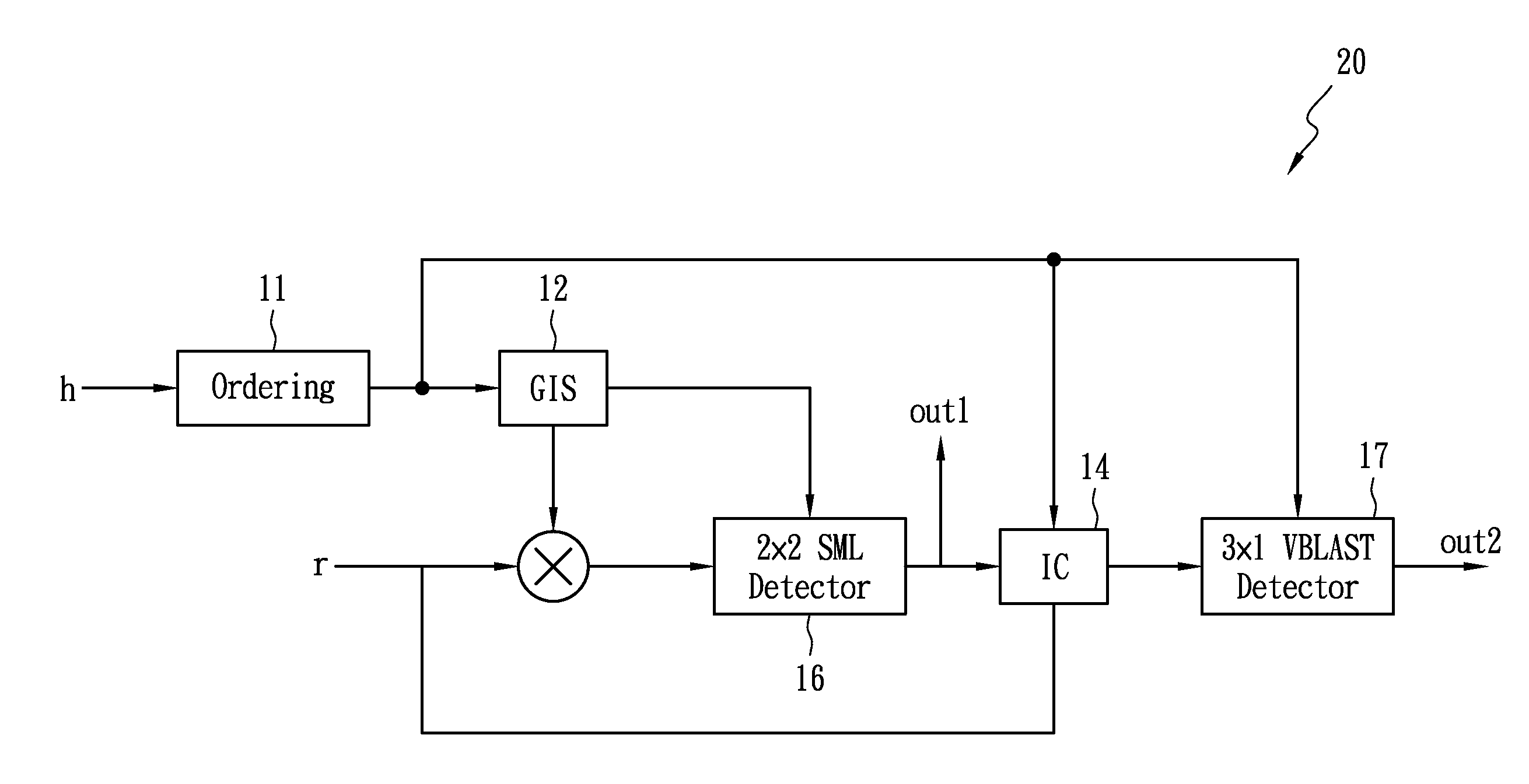
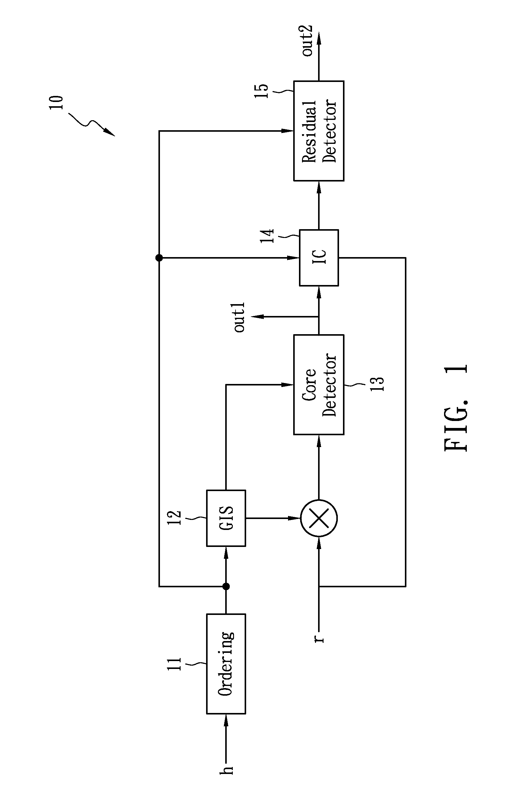
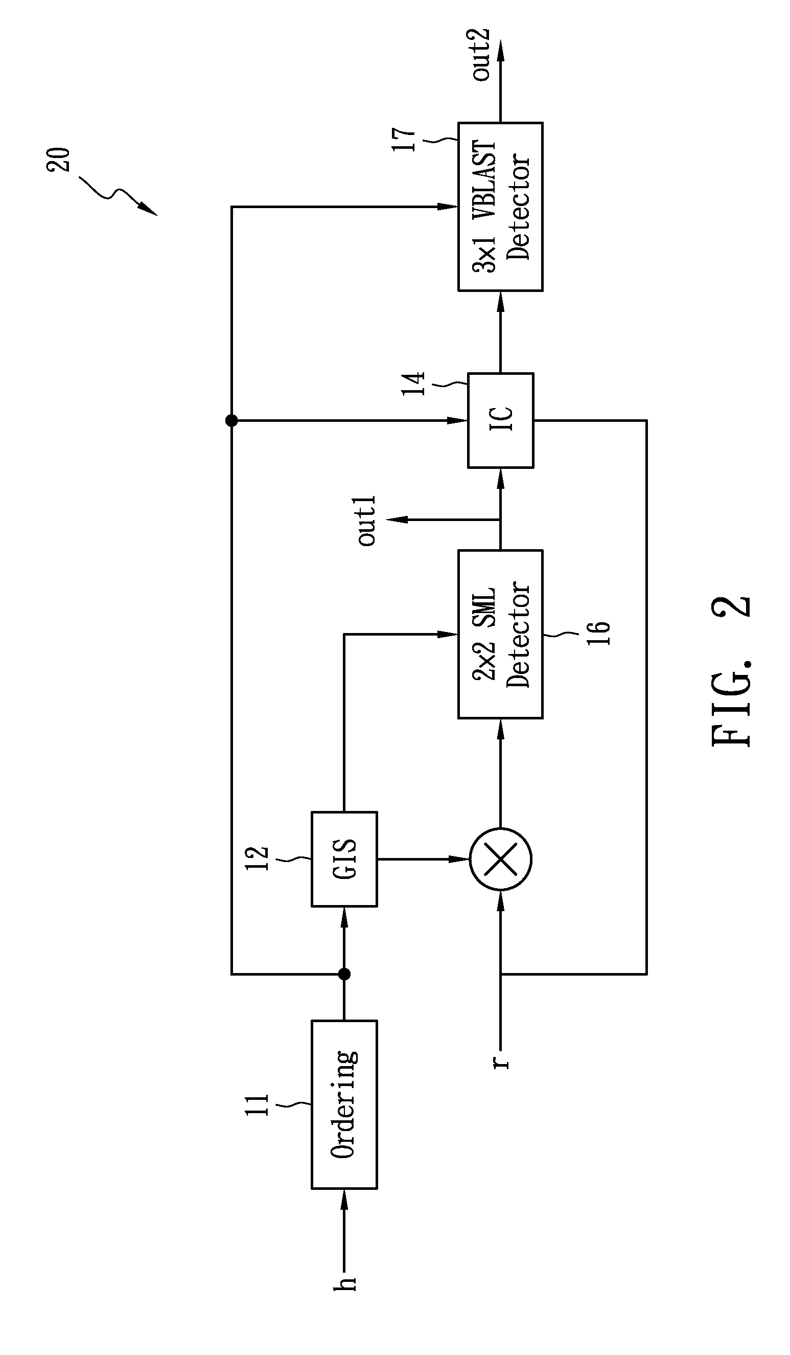
[0023]FIG. 1 illustrates a basic architecture of the scalable MIMO detector in accordance with the present invention. A scalable MIMO detector 10 comprises an ordering block 11, a Group Interference Suppression (GIS) block 12, a core detector 13, an Interference Canceling (IC) block 14 and a residua...


PUM


Abstract

A scalable Multiple-Input Multiple-Output (MIMO) detector, comprises an ordering block, a group interference suppression block, a core detector and a residual detector. The ordering block determines an order of the columns of a channel matrix including received streams based on the power thereof. The group interference suppression block coupled to the ordering block groups received streams into a core part and a residual part, the core part including a first received stream and a second received stream corresponding to the first two columns of the channel matrix in the order, the first received stream and the second received stream forming a received signal vector, and the residual part including the rest of the received streams. The core detector detects the core part based on a 2×2 Simplified Maximum Likelihood (SML) detection. The residual detector detects the residual part by Vertical Bell Laboratories Layered Space Time (VBLAST) detection.

Description

BACKGROUND OF THE INVENTION[0001](A) Field of the Invention[0002]The present invention is related to a Multiple-Input Multiple-Output (MIMO) detector and the detection method thereof, and more specifically, to a low complexity scalable MIMO detector and the detection method thereof.[0003](B) Description of the Related Art[0004]Previous researches have shown that the channel capacity increases linearly with the number of transmitter and receiver antennas. MIMO communication systems can increase the channel capacity without additional bandwidth. Therefore, MIMO is promising to achieve high data rate requirements by spatial multiplexing technology.[0005]There are many MIMO receiving technology for spatial multiplexing. These technologies can be divided into linear and non-linear detection methods. It is well known that the linear detection methods have lower complexity than non-linear ones. However, the linear detection methods have poor performance. Maximum-Likelihood (ML) detector an...

Claims


Application Information

Patent Timeline
Patent Type & Authority Applications(United States)
IPC IPC(8): H04L1/02
CPCH04L1/0656
Inventor MA, HSI PINYU, CHUNG WEN
Owner NATIONAL TSING HUA UNIVERSITY
Learn More