Flow-guiding member unit and its production method

a technology of flow-guiding members and production methods, which is applied in the direction of machines/engines, liquid fuel engines, forging/pressing/hammering apparatuses, etc., can solve the disadvantages of heavy and expensive flow-guiding members made of metal materials, large number of working steps, etc. problems, to achieve the effect of low cost, easy exchange, and sufficient mechanical strength

Active Publication Date: 2008-02-14
HONDA MOTOR CO LTD
View PDF0 Cites 28 Cited by
  • Summary
  • Abstract
  • Description
  • Claims
  • Application Information

AI Technical Summary

Benefits of technology

[0008] Accordingly, an object of the present invention is to provide a flow-guiding member unit made of a composite resin material having sufficient mechanical strength, easily exchangeable after assembled to a flow-guiding member, and producible at a low cost, and its production method.

Problems solved by technology

However, the above conventional production methods need machining, finishing, coating, etc. after the formation of vanes, resulting in a large number of working steps and difficulty in working of small complicated parts.
In addition, the flow-guiding members made of metal materials are disadvantageously heavy and expensive.
However, inevitable dimensional errors of parts make it difficult to assemble the units to a uniform shape by such production method, resulting in difficulty in fixing the units at desired positions, and needing additional steps of winding a tape to fix the units.
In addition, even when only one unit is damaged, the entire assembly should inevitably be exchanged because the units are undetachably assembled.
Accordingly, when the flow-guiding member formed by the flow-guiding member units produced by this method are damaged, only damaged units can be exchanged to new ones.
This operation requires such high skills that only skilled artisans can produce the laminate, taking an extremely long period of time and a high cost.

Method used


Image

  • Flow-guiding member unit and its production method
  • Flow-guiding member unit and its production method
  • Flow-guiding member unit and its production method

Examples


Embodiment Construction

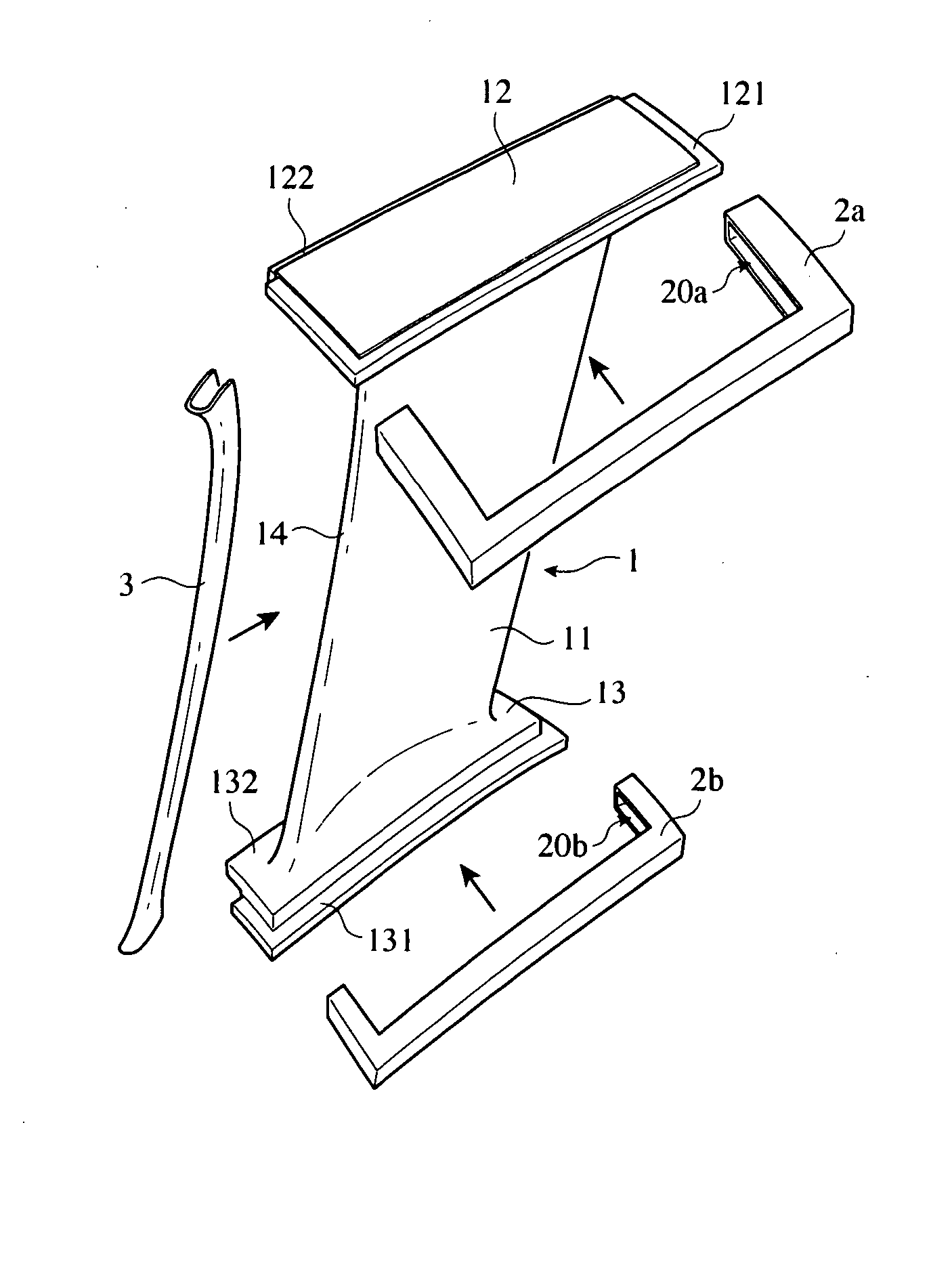
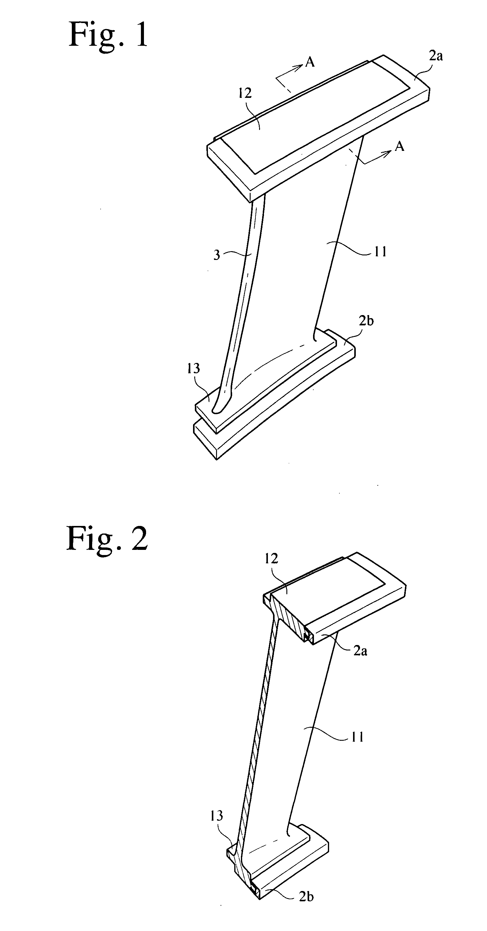
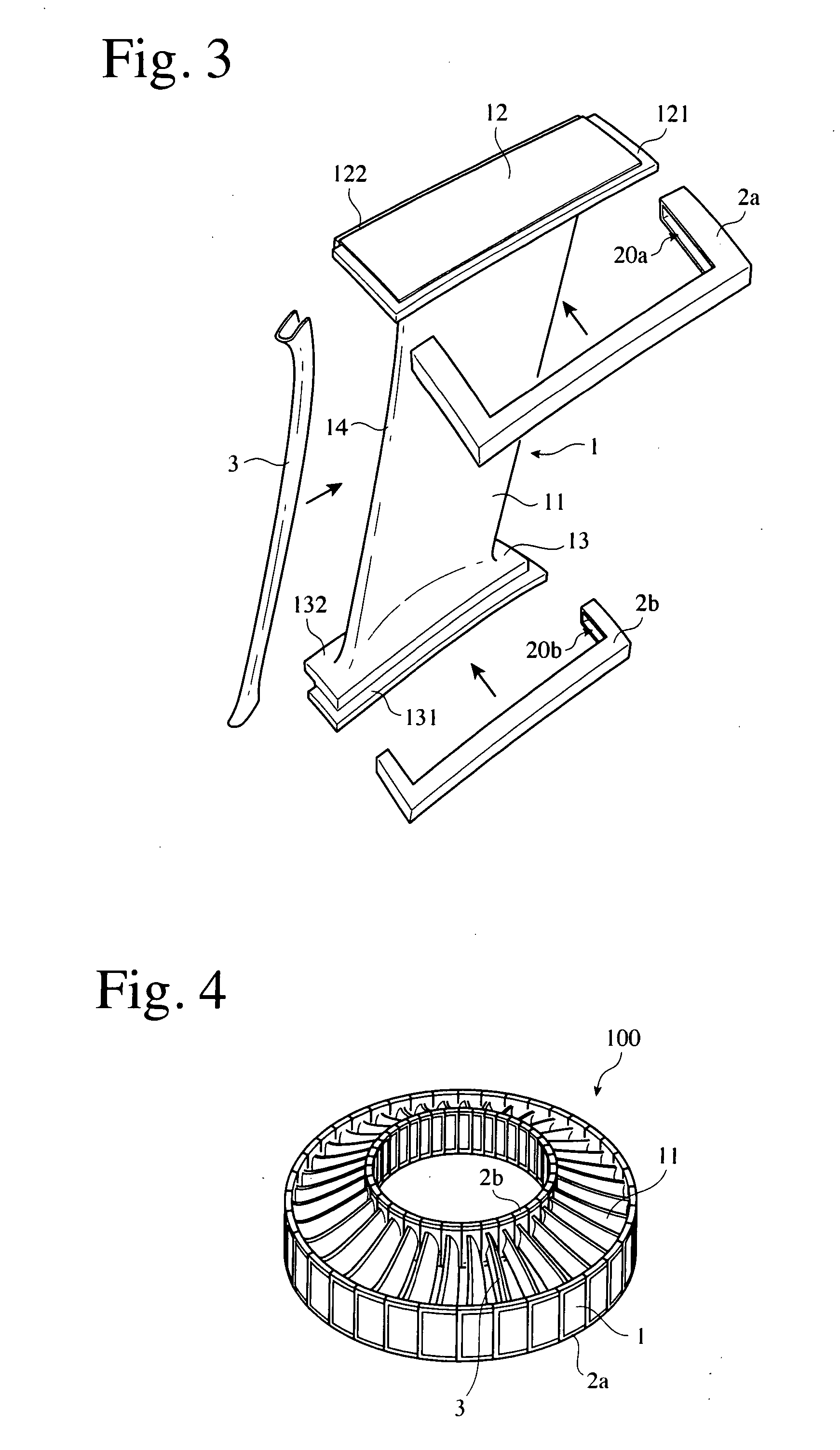
[0039]FIG. 1 shows one example of the flow-guiding member unit of the present invention. Although the flow-guiding member unit shown in FIG. 1 is in a substantially I shape, it is not restricted to the I shape, but may be in a C or Z shape. As shown in FIG. 1, the flow-guiding member unit comprises a planar vane 11, an outer platform portion 12 formed at an outer end of the vane 11, and an inner platform portion 13 formed at an inner end of the vane 11. As shown in FIG. 3, U-shaped elastic members 2a, 2b are attached to the outer platform portion 12 and the inner platform portion 13, respectively, and a protective member 3 is attached to the vane 11. As shown in FIG. 4, the connection of pluralities of flow-guiding member units forms a flow-guiding member 100 comprising pluralities of vanes and annular outer and inner platforms.

[0040] The vane 11 is a slightly curved plate, and the outer platform portion 12 and the inner platform portion 13 are substantially perpendicular to the va...


PUM

PropertyMeasurementUnit
lengthaaaaaaaaaa
thicknessaaaaaaaaaa
lengthaaaaaaaaaa

Abstract

A flow-guiding member unit used for assembling a flow-guiding member comprising pluralities of vanes, an outer platform and an inner platform, the unit comprising an integral body member comprising one vane portion, an outer platform portion, and an inner platform portion, a first elastic member attached to a step of the outer platform portion, and a second elastic member attached to a step of the inner platform portion, the body member being formed by the thermal compression of sheet-molding compounds or fiber-reinforced resin pellets, and the first and second elastic members being made of a thermoplastic elastomer.

Description

CROSS REFERENCE TO RELATED APPLICATIONS [0001] This is a continuation-in-part application of U.S. patent application Ser. No. 11 / 407,278, filed Apr. 20, 2006 and claims priority from Japanese Application No. 2005-129621 filed Apr. 27, 2005 the contents which are incorporated herein.FIELD OF THE INVENTION [0002] The present invention relates to a flow-guiding member unit used for assembling a flow-guiding member and its production method, particularly to a flow-guiding member unit having sufficient mechanical strength and light in weight, and a method for producing such a flow-guiding member unit at a low cost. BACKGROUND OF THE INVENTION [0003] Flow-guiding members for gas turbine engines, etc. are widely used for aircrafts, electric generators, etc. For instance, gas turbine engines for aircrafts are provided with stator vanes acting to guide the introduced air to rotor vanes and working as outlet guide vanes for guiding a bypass flow. The stator vanes are generally made of metal m...

Claims


Application Information

Patent Timeline
Patent Type & Authority Applications(United States)
IPC IPC(8): F01D9/04B29C41/02F01D17/12
CPCF01D5/147F01D5/282F01D9/041F04D29/023F04D29/542F05C2225/08Y10T29/49323Y02T50/672F05D2300/702F05D2300/603F05D2300/614F05D2230/40F05C2253/24F05D2230/53F05D2300/43Y02T50/60
Inventor MATSUMOTO, KEIZOTATEOKA, YASUHISA
Owner HONDA MOTOR CO LTD
Why Eureka
Try Eureka