Piezoelectric driven MEMS device

a technology of mems device and piezoelectric, which is applied in the field of piezoelectric devices, can solve the problems of electrostrictive effect, difficult to adjust the capacitance value of variable capacitance obtained, and beam warping upward or downward, and achieve excellent reproducibility and reliability

Inactive Publication Date: 2008-02-21
KK TOSHIBA
View PDF14 Cites 22 Cited by
  • Summary
  • Abstract
  • Description
  • Claims
  • Application Information

AI Technical Summary

Benefits of technology

[0017]The present invention has been made in view of these circumstances and an object of the present invention is to provide a piezoelectric driven MEMS device having the distance between the a

Problems solved by technology

Therefore, there is a very serious problem that the beam is warped upward or downward by slight residual stress in the material of the beam.
As a result, it is very difficult to adjust the capacitance value of the variable capacitance obtained before and after applying the voltage in conformity with the design and keep the drive voltage of the switch at a constant value.
Therefore, there are conflicting problems: a material that is great in electrostrictive effect is difficult to control the residual strain and a material that is comparatively easy in control of residual strain is small in elect

Method used


Image

  • Piezoelectric driven MEMS device
  • Piezoelectric driven MEMS device
  • Piezoelectric driven MEMS device

Examples


first embodiment

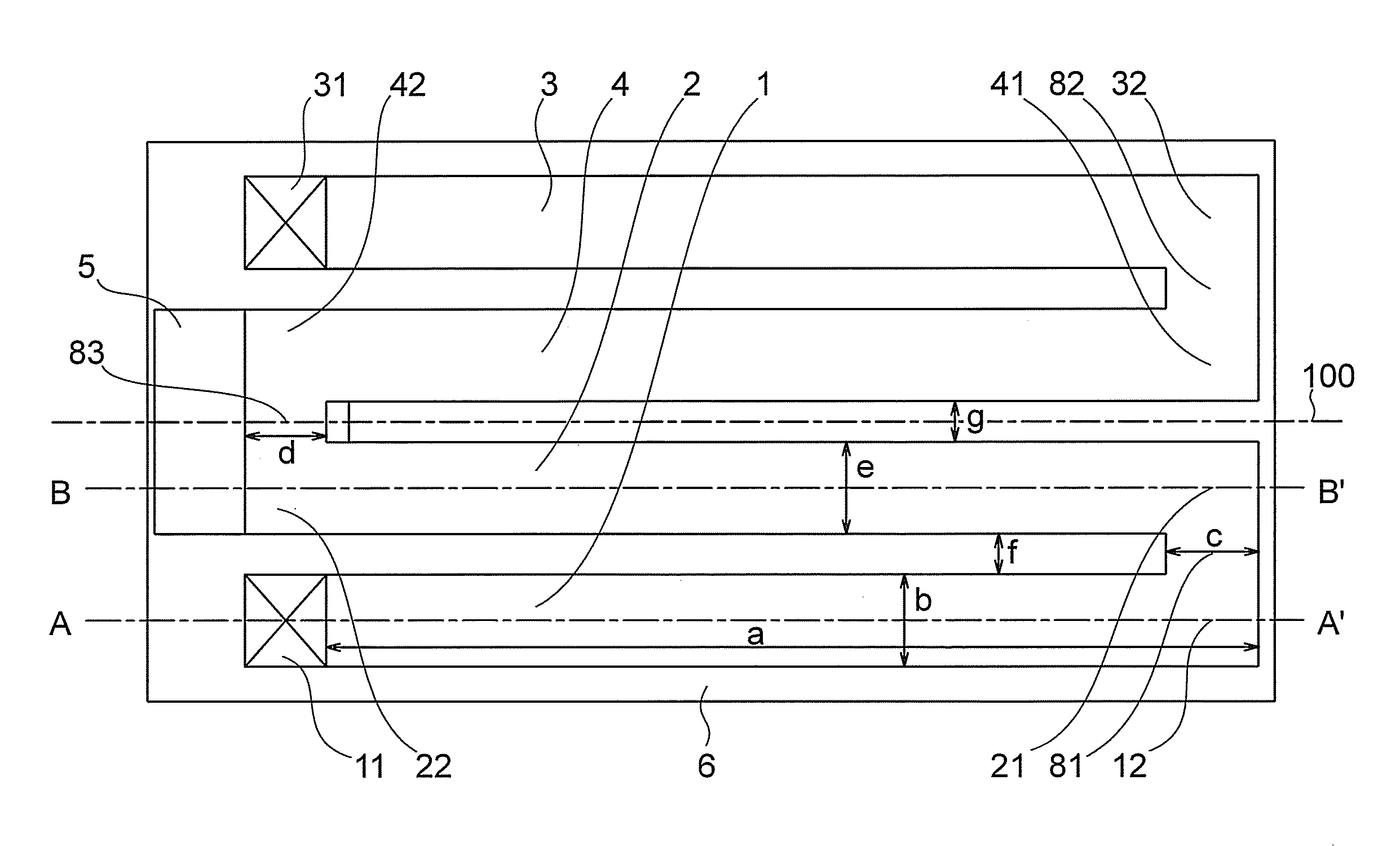
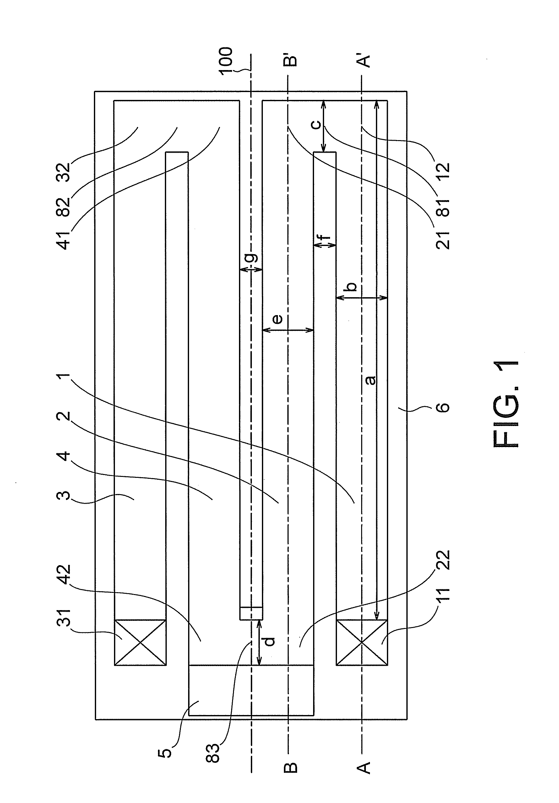
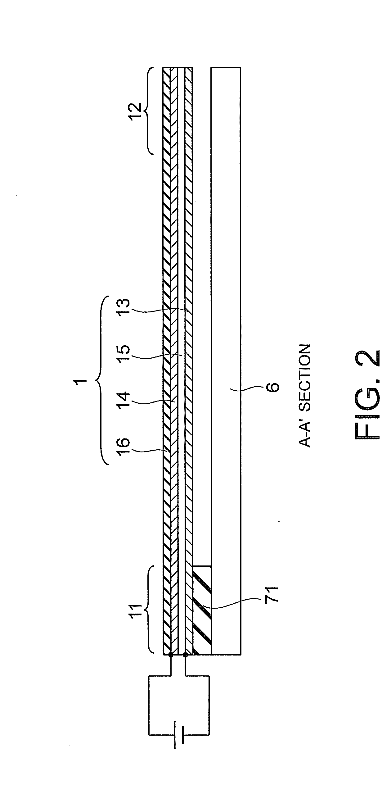
[0041]A piezoelectric driven MEMS device according to a first embodiment of the present invention will now be described with reference to FIGS. 1 to 5. The piezoelectric driven MEMS device according to the present embodiment is a variable capacitor, and includes first to fourth actuators 1, 2, 3 and 4 as shown in FIG. 1. The second to fourth actuators 2, 3 and 4 are provided in parallel with the first actuator 1, and have the same length (dimension in a direction of extension of the actuators (lengthwise direction)) as that of the first actuator 1. A first end of the first actuator 1 is a fixed end 11, and it is fixed to a substrate 6 through an anchor 71. A second end (connection end) 12 of the first actuator is connected to a first end 21 of the second actuator 2 by a first connection portion 81. A second end of the second actuator 2 is an action end 22, and a movable electrode is provided thereon. A first end of the third actuator 3 is a fixed end 31, and it is fixed to the subst...

first modification

(First Modification)

[0050]A piezoelectric driven MEMS device according to a first modification of the first embodiment will now be described. The piezoelectric driven MEMS device according to the present modification differs from the first embodiment in the connection form of the lower electrode and the upper electrode of the first to fourth actuators, and consequently in the operation form of the actuators.

[0051]In the present modification, the lower electrode 13 of the first actuator 1 is insulated from the lower electrode 23 of the second actuator 2, and the lower electrodes 23, 33 and 43 respectively of the second to fourth actuators 2, 3 and 4 are connected together, as shown in FIG. 6. In addition, the upper electrode 34 of the third actuator 3 is insulated from the upper electrode 44 of the fourth actuator 4, and the upper electrodes 14, 24 and 44 respectively of the first, second and fourth actuators 1, 2 and 4 are connected together, as shown in FIG. 7. Therefore, the conne...

second modification

(Second Modification)

[0056]A piezoelectric driven MEMS device according to a third modification of the first embodiment will now be described with reference to FIG. 8. The piezoelectric driven MEMS device according to the present modification has a configuration obtained by dividing the fixed electrode 5 in the first embodiment shown in FIG. 1 into a first fixed electrode 53 and a second fixed electrode 54.

[0057]If the piezoelectric driven MEMS device is a variable capacitor (if a dielectric film is provided on the fixed electrodes 53 and 54) in the present modification, a first variable capacitor is formed between the first fixed electrode 53 and the action end 22 of the second actuator 2 and a second variable capacitor is formed between the second fixed electrode 54 and the action end 42 of the fourth actuator 4. A high frequency signal flows through the first fixed electrode 53, the first variable capacitor, the action end 22 of the second actuator, the action end 42 of the fourt...


PUM


Abstract

It is made possible to provide a piezoelectric driven MEMS device having the distance between the action end and the fixed electrode which is kept constant regardless of whether the residual strain is large or small and having a mechanism which is excellent in reproducibility and reliability. Two piezoelectric driven actuators each having a folded beam structure are disposed in parallel and in a line-symmetric manner, and connected to each other in the vicinity of an action end.

Description

CROSS-REFERENCE TO RELATED APPLICATION[0001]This application is based upon and claims the benefit of priority from prior Japanese Patent Application No. 2006-173605 filed on Jun. 23, 2006 in Japan, the entire contents of which are incorporated herein by reference.BACKGROUND OF THE INVENTION[0002]1. Field of the Invention[0003]The present invention relates to a piezoelectric driven MEMS device.[0004]2. Related Art[0005]Recently, variable capacitors and switches using actuators fabricated by using the MEMS (Micro-electro-mechanical System) technique are drawing the attention. A movable electrode is formed on a beam which is supported in the air over a substrate. A fixed electrode is formed on an opposed substrate. The beam is driven by electrostatic force, electro-thermal force, electromagnetic force, piezoelectric force, and so on. The distance between the movable electrode and the fixed electrode is changed. A variable capacitor or a switch is thus formed.[0006]Especially in a varia...

Claims


Application Information

Patent Timeline
IPC IPC(8): H01L41/047
CPCH01G5/16H01H2057/006H01H57/00H01L29/00
Inventor KAWAKUBO, TAKASHINAGANO, TOSHIHIKONISHIGAKI, MICHIHIKO
Owner KK TOSHIBA
Why Eureka
Try Eureka