Clip-on night vision device

a night vision device and clip-on technology, applied in the field of night vision devices, can solve the problems of heavy weight and the added weight of two sighting systems that must be carried, and achieve the effects of simple and reliable, precise, reliable and simpl

Active Publication Date: 2008-02-21
LITTON SYST INC
View PDF22 Cites 18 Cited by
  • Summary
  • Abstract
  • Description
  • Claims
  • Application Information

AI Technical Summary

Benefits of technology

[0011]A primary objective of the present invention is to provide a simple and reliable method of setting boresight alignment with a mechanism that would hold boresight alignment through extended weapon shock. Also, since the optical sight on the man portable weapon is normally “boresighted” for accuracy before use, a removable night viewer device that cooperates with the mounted scope greatly reduces the need to remove the optical scope or otherwise changing the boresight alignment of the scope.
[0012]To achieve the nec

Problems solved by technology

A problem with day/night and other types of combined sights is the bulk and the added wei

Method used


Image

  • Clip-on night vision device
  • Clip-on night vision device
  • Clip-on night vision device

Examples


Embodiment Construction

[0026]So that the manner in which the above recited features, advantages and objects of the present invention are attained can be understood in detail, more particular description of the invention, briefly summarized above, may be had by reference to the embodiment thereof that is illustrated in the appended drawings. In all the drawings, identical numbers represent the same elements.

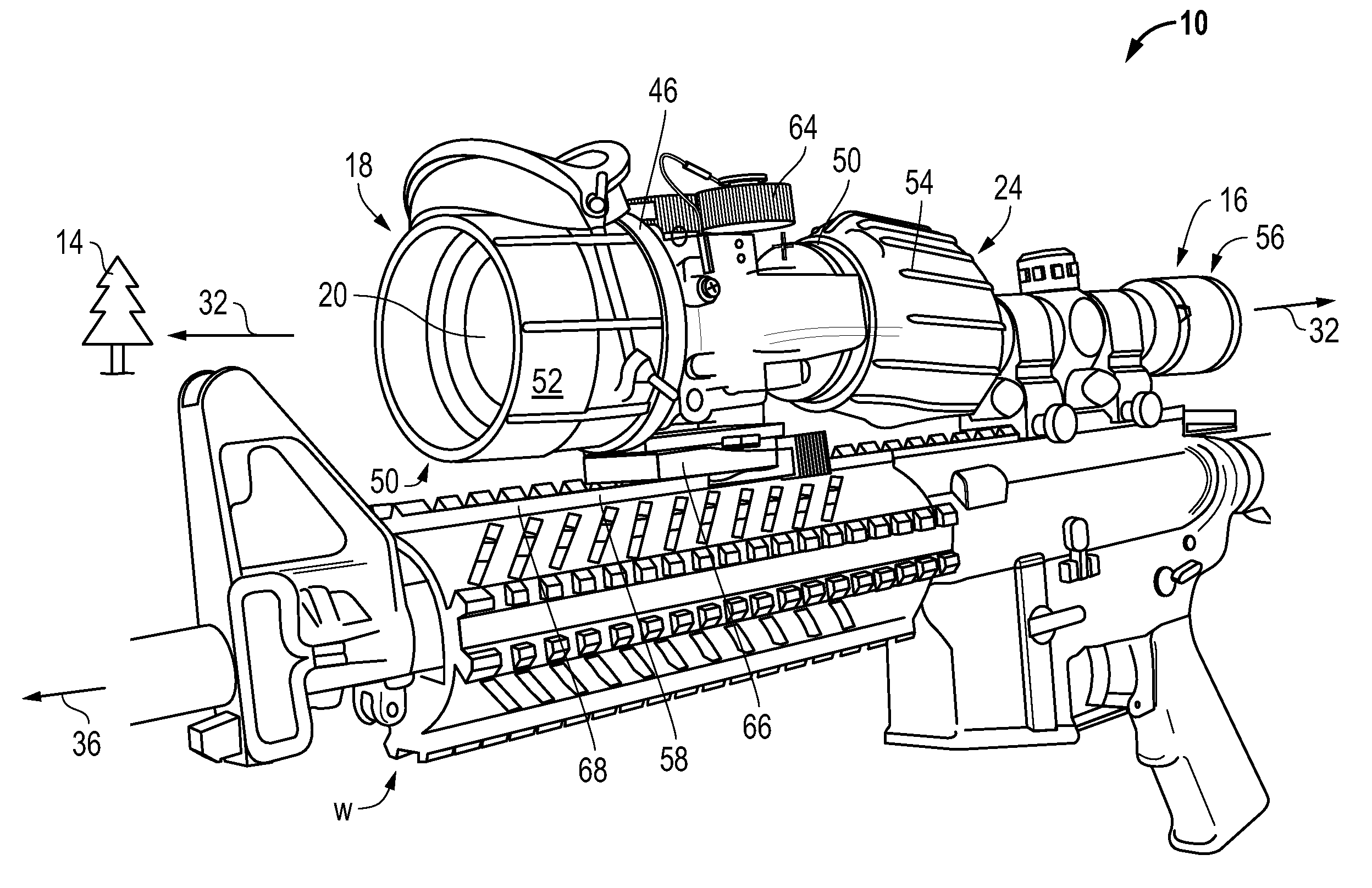
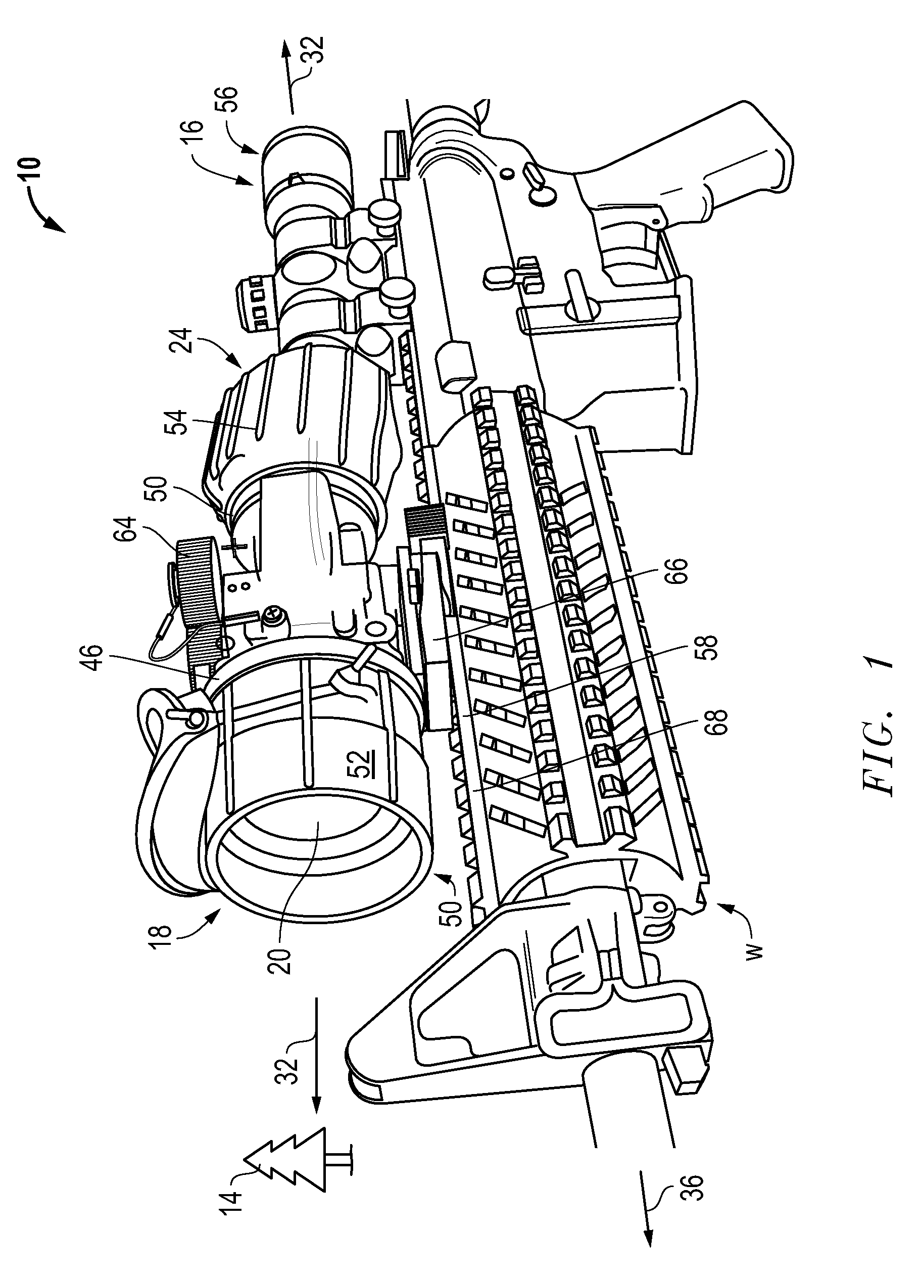
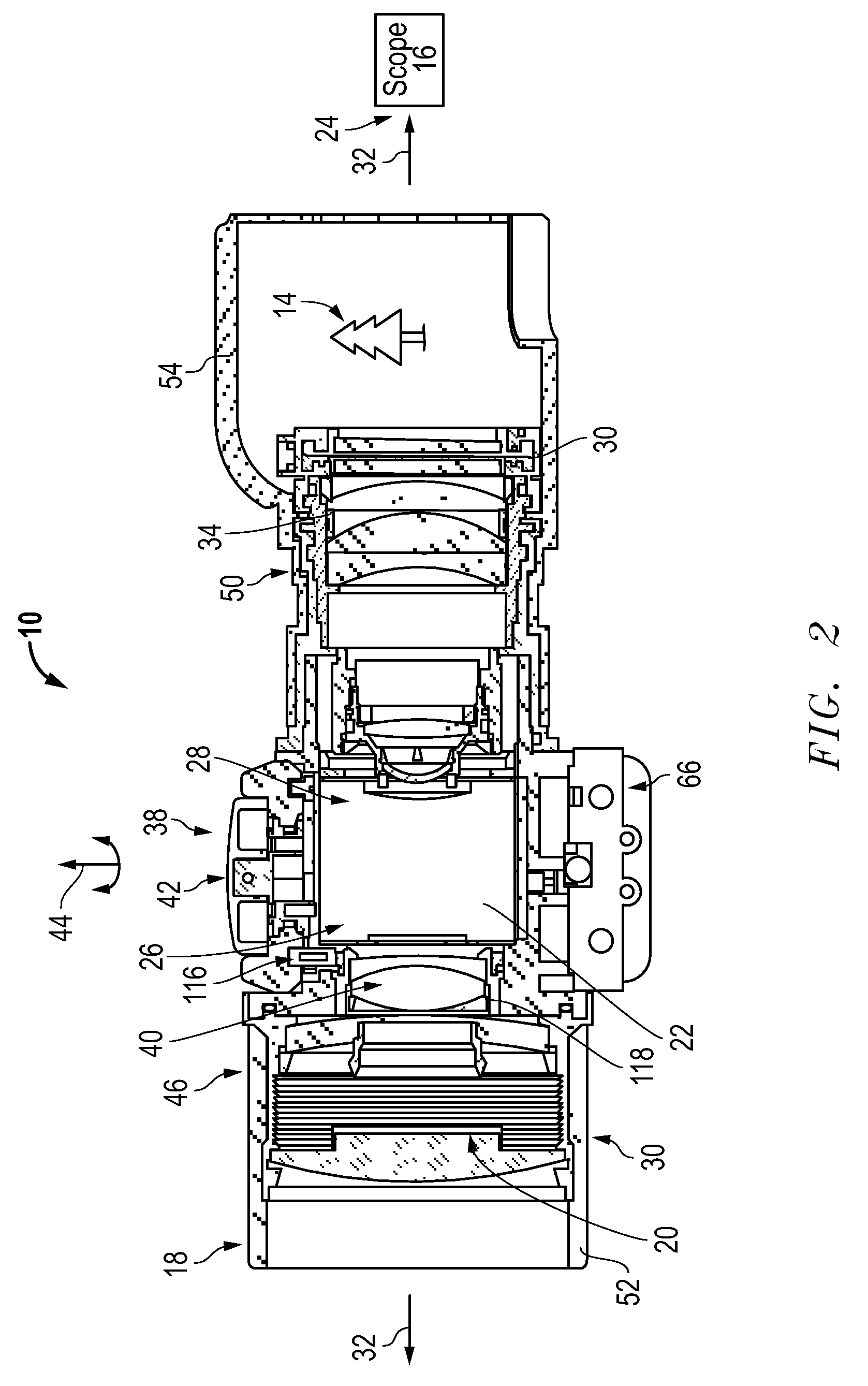
[0027]A mountable clip-on night viewer device (“CNVD”) 10 is adaptable to generate an enhanced image 12 of a scene 14 suitable to be viewed through a Rifle Combat Optic (RCO) or optical scope 16. An input end 18 of the night viewer device 10 receives the input image to be enhanced through an objective lens assembly 20. An image enhancing unit 22 enhances the input image of the scene into a desired format. The image to be enhanced is optically transmitted to an ocular lens end 24 of the optical scope 16 after being received through an input end 26 of the image enhancing unit 22. An output image display u...


PUM


Abstract

A night viewer (10) is adaptable to generate an enhanced image suitable for viewing through an optical scope (16). An input end (18) of the viewer (10) receives the image to be enhanced through an objective lens (20). An image enhancing unit (22) enhances the image. The enhanced image is optically transmitted from a display (28) to the ocular lens (24) of the scope (16). The display (28) is operably connected with the image enhancing unit (22) to display the enhanced image. A Risley prism (30) located in an image path (32) is used to controllably adjust and to maintain boresight alignment (36).

Description

BACKGROUND OF THE INVENTION[0001]1. Technical Field[0002]The invention relates to the field of night viewer type devices for enhancing the image of a scene to he viewed, and more particularly to weapon mounted night viewer devices suitable for combined use with known man-portable weapon sights.[0003]2. Background Art[0004]Single unit, day / night sights have been used by military and law enforcement personnel to aim weapons used in both day time and night time conditions. Typically, a day / night sight includes an objective lens, a reticle and an eyepiece in series with parallel, but separate, day and night channels. A channel selector or optical switch may be used to alternatively direct an image of a target into the day or night channel.[0005]In a day / night sight, the objective lens and the eyepiece may be telescopic to provide a magnified image of the target. The day channel generally uses ambient light to generate an image of the target. The image may be projected or electronically ...

Claims


Application Information

Patent Timeline
IPC IPC(8): G02B21/36
CPCF41G1/38G02B23/12F41G11/003
Inventor SAUTER, KENNETH W.DOSTER, RODNEY L.MORLEY, ROLAND M.
Owner LITTON SYST INC
Why Eureka
Try Eureka