Wiring Board for Light-Emitting Element

a light-emitting element and wiring board technology, applied in the direction of printed circuit aspects, electrical apparatus construction details, electric connection formation of printed elements, etc., can solve the problems of high process cost, inability to cope with problems, deterioration of connection reliability, etc., to suppress cracks, increase adhesion strength, and suppress cracks

Inactive Publication Date: 2008-02-21
KYOCERA CORP
View PDF10 Cites 151 Cited by
  • Summary
  • Abstract
  • Description
  • Claims
  • Application Information

AI Technical Summary

Benefits of technology

[0021] It is further desired that the end surface of the heat-conducting pole-like conductor on the side of the mounting region (end surface of the upper side) and the peripheral edges thereof are covered with a covering layer containing a metal or a resin and that the end surface of the heat-conducting pole-like conductor on the side opposite to the side of the mounting region (end surface of the lower side) and the peripheral edges thereof are covered with a covering layer containing at least one of those selected from the group consisting of a metal, ceramics and a resin. Provision of the covering layer on the end surface on the upper side of the heat-conducting pole-like conductor or on the end surface on the lower side thereof, too, makes it possible to relax the difference in the thermal expansion between the pole-like conductor and the insulating substrate and to suppress the occurrence of cracks on the boundary between the end surface of the pole-like conductor and the insulating substrate.
[0022] It is further desired that the heat-conducting pole-like conductor has a thermal conductivity of not smaller than 80 W / m·K from the standpoint of quickly radiating the heat generated by the light-emitting element.
[0023] Further, it is desired that the heat-conducting pole-like conductor is formed by using a metal material and a ceramic material. Use of the metal / ceramic pole-like conductor makes it easy to control, for example, the coefficient of thermal expansion. Upon bringing the coefficient of thermal expansion close to that of the insulating substrate, it is made possible to suppress the occurrence of cracks caused by the mismatching in the thermal expansion from the from that of the insulating substrate. It is further allowed to increase the adhering strength between the pole-like conductor and the insulating substrate, which is advantageous even from the standpoint of conducting the co-firing with the insulating substrate.
[0024] In the present invention, the heat-conducting pole-like conductor can be incorporated in a portion of the electric circuit. In this case, no conduction terminal is necessary offering advantage from the standpoint of decreasing the size of the wiring board for light-emitting element.
[0025] The heat-conducting pole-like conductor may be formed by using a plurality of layers having different coefficients of thermal expansion or different thermal conductivities. When the heat-conducting pole-like conductor is formed relying upon the above laminated-layer structure, the coefficients of thermal expansion and the thermal conductivities of the layers are varied, e.g., a difference in the thermal expansion is decreased between the layer on the side of the mounting region and the light-emitting element that is mounted. In this case, the layer of the lower side is set to possess a high thermal conductivity irrespective of the coefficient of thermal expansion to enhance the heat-radiating performance yet maintaining reliability.
[0026] In the light-emitting device mounting the light-emitting element on the wiring board for light-emitting element of the present invention as described above, heat generated by the light-emitting element can be quickly radiated out of the device, suppressing a decrease in the brightness caused by heat generated by the light-emitting element.

Problems solved by technology

The insulating board made of alumina has a coefficient of thermal expansion of about 7.0×10⁻⁶ / ° C. and a difference in the coefficient of thermal expansion from the printed board does not cause any practical problem.
However, the aluminum nitride is accompanied by such defects that the starting material thereof is expensive, that the firing must be effected at a high temperature since it can be sintered difficultly and that the process cost is high.
Besides, due to its coefficient of thermal expansion which is as small as 4 to 5×10⁻⁶ / ° C., the wiring board using the aluminum nitride insulating substrate arouses a problem of deteriorating the connection reliability when it is mounted on a general-purpose printed board (having a coefficient of thermal expansion of not smaller than 10×10−6 / ° C.) due to a difference in the thermal expansion.
On the other hand, an insulating substrate made of a resin has a coefficient of thermal expansion close to that of the printed board and poses no problem concerning the reliability of mounting the printed board, but has a thermal conductivity which is as very low as 0.05 W / m·K, and is not quite capable of coping with the problem related to the heat.
When used in the near ultraviolet-ray band for extended periods of time, therefore, the insulating board is blackened causing a decrease in the brightness of the light-emitting element.

Method used


Image

  • Wiring Board for Light-Emitting Element
  • Wiring Board for Light-Emitting Element
  • Wiring Board for Light-Emitting Element

Examples


Embodiment Construction

[Wiring Board for Light-Emitting Element]

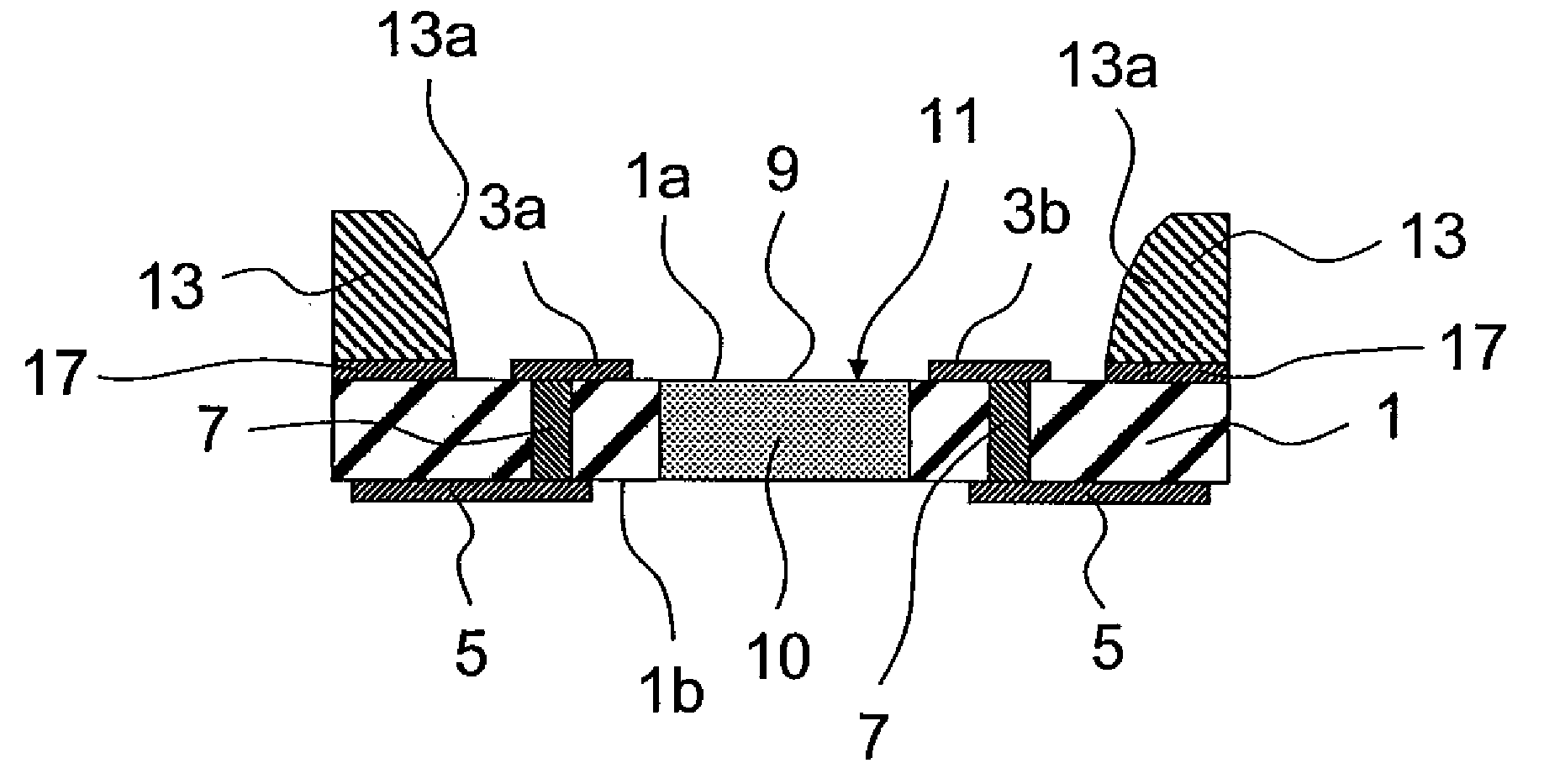
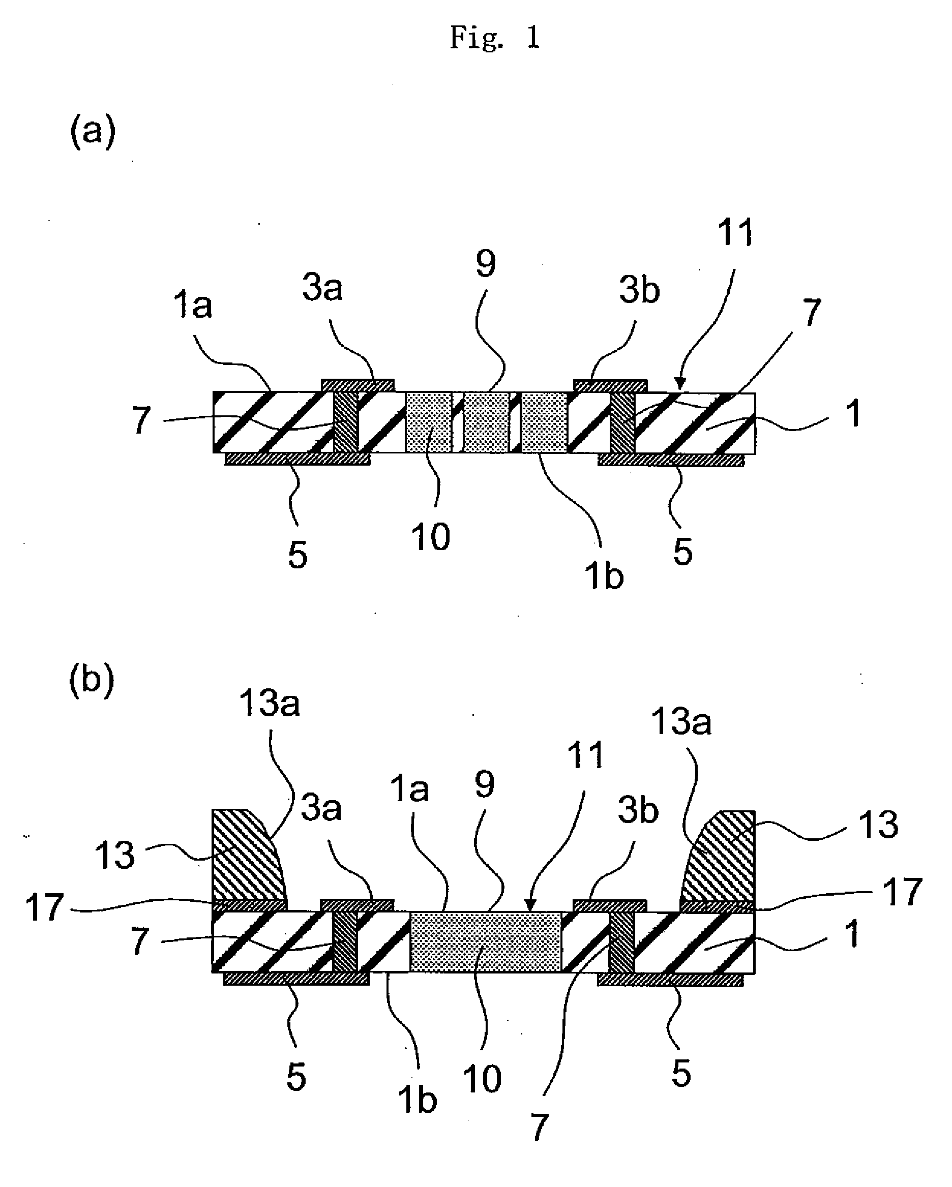
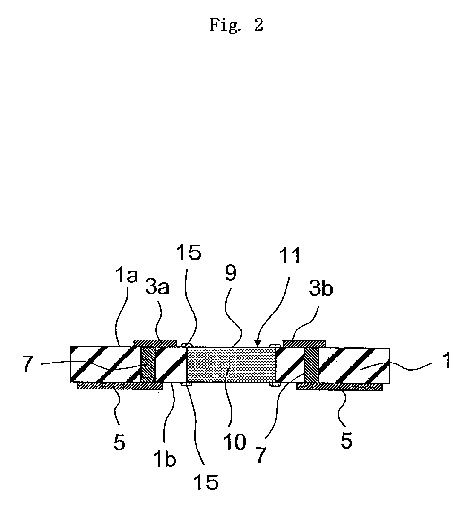
[0035] In FIGS. 1(a) and 1(b) illustrating a representative structure of a wiring board for light-emitting element of the present invention, the wiring board generally designated at 11 includes a ceramic insulating substrate 1, conductor layers (connection terminals) 3a and 3b formed on one surface 1a of the insulating board 1, conductor layers (external electrode terminals) 5 formed on the other surface 1b of the insulating substrate 1, and via-conductors 7 formed through the insulating substrate 1 so as to electrically connect the conductor layers 3a, 3b to the conductor layers 5.

[0036] On the surface 1a of the insulating substrate 1, there is formed a mounting region 9 between one conductor layer 3a and another conductor layer 3b for mounting a light-emitting element that will be described later. That is, the conductor layers 3a and 3b are electrically connected to the light-emitting element (not shown in FIGS. 1(a) and 1(b)) mounted on ...


PUM


Abstract

A wiring board for light-emitting element, comprising a ceramic insulating substrate, and a conductor layer formed on the surface or in the inside of the insulating substrate, and having a mounting region mounting a light-emitting element on one surface of the insulating substrate; wherein the insulating substrate is provided with a heat-conducting pole-like conductor having a thermal conductivity higher than that of said insulating substrate; and the heat-conducting pole-like conductor is extending through the insulating substrate in the direction of thickness thereof from the light-emitting element mounting region of the insulating substrate, and is formed by the co-firing with the insulating substrate. The wiring board is produced inexpensively by co-firing, features excellent heat-radiating performance, is capable of quickly radiating the heat from the light-emitting element when the light-emitting element is mounted, and effectively prevents a decrease in the brightness of the light-emitting element caused by the heat.

Description

TECHNICAL FIELD [0001] The present invention relates to a wiring board for mounting a light-emitting element such as a light-emitting diode (LED). BACKGROUND ART [0002] So far, a light-emitting device obtained by mounting an LED on a wiring board features a very high light-emitting efficiency, emits light producing heat in amounts smaller than that of incandescent lamps, and has been used for a variety of applications. However, the light-emitting device of this kind emits light in amounts smaller than those of incandescent bulbs and fluorescent lamps, and is used not for illumination purposes but as a source of light of an indicator consuming a current which is as very small as about 30 mA. The light-emitting device of this kind consumes a small electric power generating a small amount of heat, and has, hence, been realized chiefly in a structure of a so-called bullet type by burying the light-emitting element (LED) in a plastic insulating substrate (see patent document 1). [0003] A...

Claims


Application Information

Patent Timeline
Patent Type & Authority Applications(United States)
IPC IPC(8): H05K7/20H01L33/48H01L33/64H05K1/02H05K1/03H05K3/40
CPCH01L33/486H01L33/642H01L2924/01322H01L2224/73265H01L2224/48227H01L2224/48091H01L2224/32225H05K2201/10106H05K3/4629H05K1/0206H05K1/0306H05K3/4061H01L2924/00014H01L2924/00H01L2924/181H01L2924/00012
Inventor HASEGAWA, TOMOHIDEIZUMI, MINAKOSASAKI, YASUHIROHAMADA, NORIAKIOKAMURA, TAKUJIMOTOMURA, KOICHI
Owner KYOCERA CORP
Why Eureka
Try Eureka