

Dual Diaphragm Electroacoustic Transducer
a transducer and diaphragm technology, applied in the direction of transducer types, frequency/directions obtaining arrangements, electrical equipment, etc., can solve the problem of disclosed transducers with less than optimal conversion efficiency
Active Publication Date: 2008-02-21
SONION NEDERLAND
View PDF16 Cites 45 Cited by
- Summary
- Abstract
- Description
- Claims
- Application Information
AI Technical Summary
Benefits of technology
[0017] According to another advantageous embodiment of the invention, the transducer housing comprises a magnetically conductive first housing portion that surrounds or encloses a centrally positioned magnet assembly such as a single rare-earth type magnet like a Nd—Fe—B magnet. The magnet assembly is operatively secured to an inner side wall portion of the first magnetically conductive portion of the housing. The attachment between the magnet assembly and the first housing portion may be based on gluing or welding. Preferably, a peripheral portion of the magnet assembly abuts the inner side wall portion of the first housing portion to make effective use of the limited space available inside a miniature transducer. The magnet assembly is preferably of simple shape such as annular or disc-shaped, cylindrical or rectangular but may have other shapes such as generally polygonal. A mating internal wall shape of the first magnetically conductive portion of the housing is preferably selected. The first housing portion may advantageously surround and enclose the first moveable assembly and the second moveable assembly so as to provide a compact and preferably self-contained dual-diaphragm transducer core.
[0022] According to particular advantageous embodiment of the invention, the transducer housing comprises a first housing portion of magnetically permeable material surrounding the permanent magnet assembly or assemblies and the common magnetic flux path comprises the first housing portion. This allows a portion of the transducer housing to serve an additional function combing with the common magnetic flux path. One or several otherwise needed ferromagnetic members to conduct magnetic flux between the first and second magnetic gaps within the common flux path are no longer required. This feature leads to fewer parts and simplified assembly of the transducer. The first housing portion may extend axially to surround the first and second moveable assemblies. The transducer housing may comprise a second housing portion extending above and covering the first diaphragm to form a first front chamber having a first side facing or frontally facing sound aperture a third housing portion extending above and covering the second diaphragm to form a second front chamber having a second side facing or frontally facing sound aperture. The first and second housing portions may be shaped as respective lids comprising magnetically permeable material, such as a ferromagnetic alloy, and / or injection molded plastic parts.
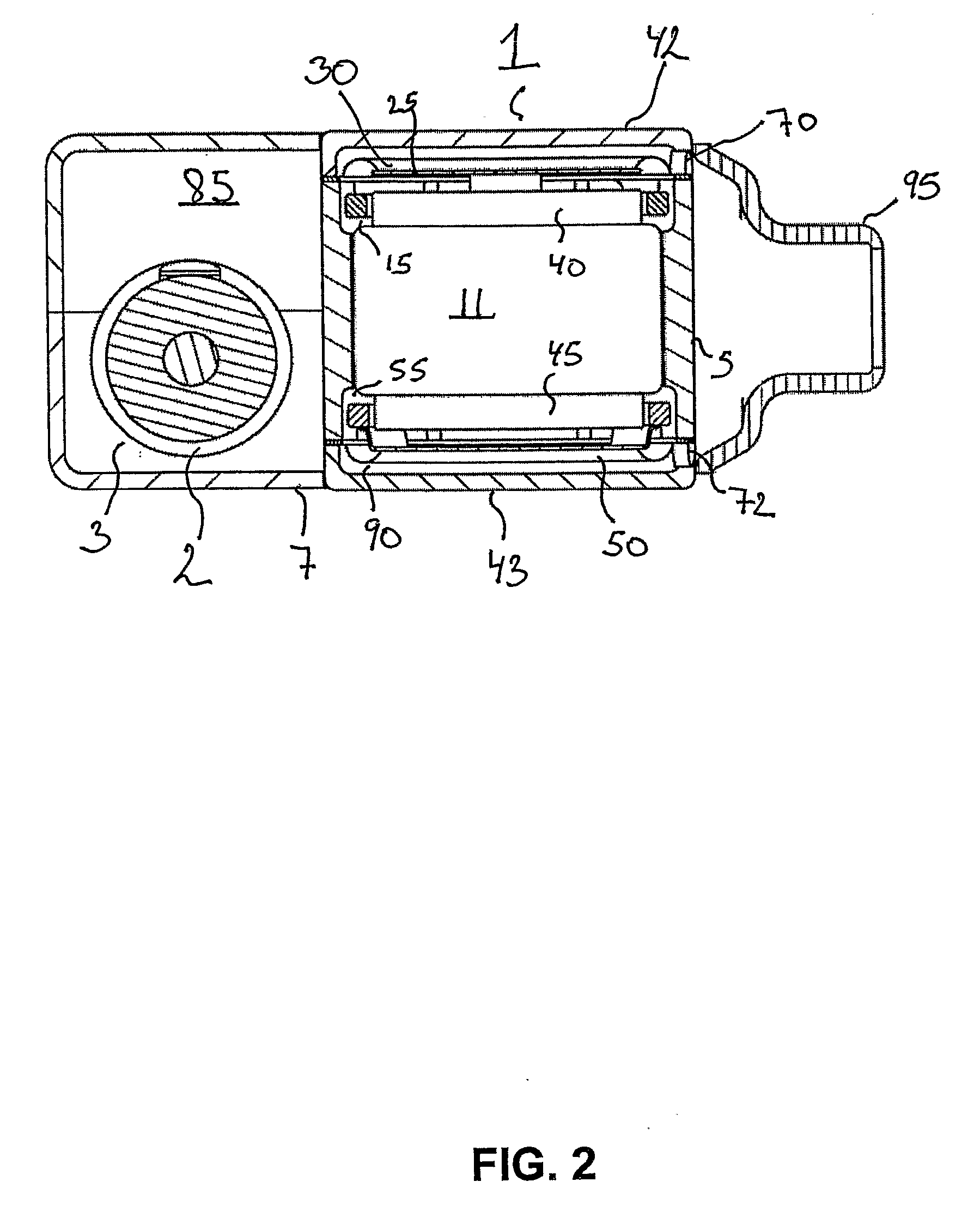
[0025] The upper and lower back chambers may comprise respective back chamber sound apertures or the common back chamber may comprise a back chamber sound aperture. A flexible way to control for back chamber volume of the present transducer is provided by an embodiment wherein an outer transducer housing portion forming a substantially closed acoustical chamber positioned adjacent to an outer surface portion of the first housing portion comprises an acoustical connection between back chamber sound aperture or apertures and the closed acoustical chamber to provide a joint and enlarged effective back chamber of the miniature electroacoustic transducer. A particularly attractive transducer in accordance with this latter embodiment is disclosed in connection with FIG. 2 below. The transducer may be embodied as two substantially separate sub-assemblies integrated into a single miniature loudspeaker by fixedly attaching the separate sub-assemblies to each other by welding, press fitting or gluing etc. A first subassembly comprises a cylindrical, or any other suitable shape, acoustical driver or core and the second subassembly comprises an outer housing having for example a generally rectangular shape. The back chamber sound aperture or apertures connecting the closed acoustical chamber to the back chamber(s) of the acoustical driver provides a simple and flexible design which allows tailoring transducer performance to specific applications by solely changing dimensions of the rectangular outer housing while retaining all dimensions of the acoustical driver.
[0026] The miniature electroacoustic transducer according to the present invention may comprise a centrally positioned magnetically permeable structure forming part of the common magnetic flux path so as to conduct magnetic flux between the first and second magnet assembly and / or between the first and second magnetic gaps. This centrally positioned magnetically permeable structure may additionally form part of a second magnetic flux path for embodiments of the invention that incorporates unidirectional or discontinuous magnetic gaps and have first and second separate common magnetic flux paths. This centrally positioned magnetically permeable structure preferably comprises a laminated structure of magnetically permeable material such as a ferromagnetic alloy like Vacoflux. The outer surface of the centrally positioned magnetically permeable structure may advantageously provide an inner boundary surface of at least the first and second magnetic gaps and, optionally, an inner boundary surface all magnetic gaps of the electroacoustic transducer.
[0035] According to particularly attractive embodiments of the invention, the first and second magnet assembly and the first and second moveable assemblies form a mirror symmetrical physical arrangement or layout around a central plane extending parallelly to the first and second diaphragms. The transducer housing and / or sound aperture may additionally be symmetrically constructed and arranged around the central plane. According to this electroacoustic transducer design, magnetic poles between the upper and lower magnet assembly may advantageously be swapped so that first and second magnetic fluxes are substantially oppositely directed. All embodiments of the invention may benefit from employing first and the second moveable assemblies of substantially identical masses to reduce vibration output of the electroacoustic transducer during loudspeaker operation.
Problems solved by technology
While the disclosed miniature transducer has a number of noticeable advantages such as very small height, the need for folded conductive coils and separate magnetic flux paths around each unidirectional gap may render the disclosed transducer with less than optimal conversion efficiency.
Method used
View moreImage
Smart ImageViewing Examples

Examples
first embodiment
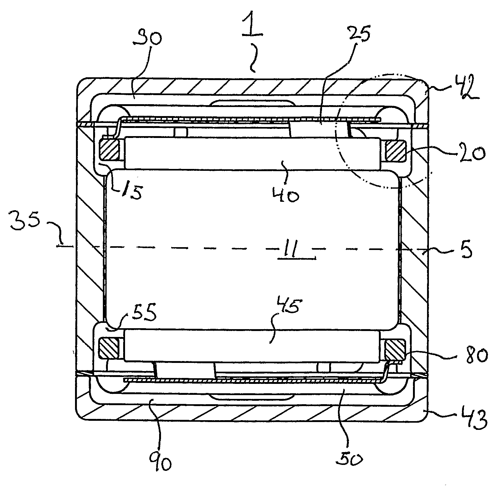
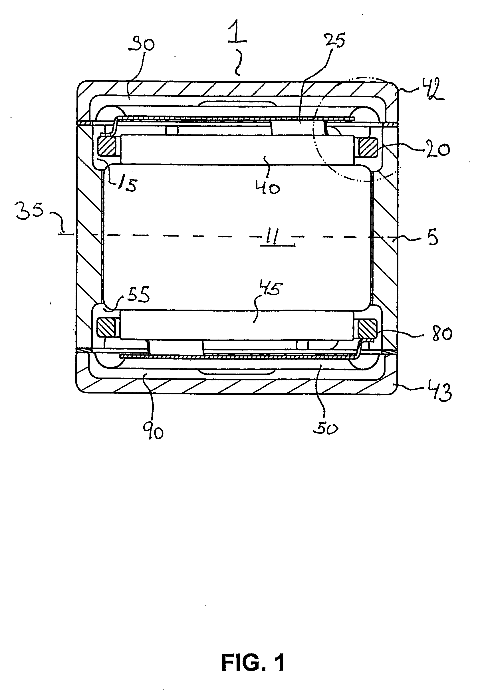
[0038]FIG. 1 shows an axial cross-sectional view of a cylindrical dual-diaphragm speaker according to the invention,
second embodiment
[0039]FIG. 2 shows a vertical cross-sectional view of the invention in form of a hearing aid receiver comprising an internally mounted cylindrical dual-diaphragm speaker,
[0040]FIG. 3 shows a horizontal cross-sectional view of the hearing aid receiver of FIG. 2,
[0041]FIG. 4 is a 3D perspective view of internal parts of the hearing aid receiver of FIG. 2,
third embodiment
[0042]FIG. 5a-b show vertical and horizontal cross-sectional views of a rectangular dual-diaphragm receiver or loudspeaker comprising an inner central cylindrical magnet structure according to the invention,
Login to View More PUM
 Abstract
The present invention relates to dual-diaphragm electroacoustic transducers wherein a common magnetic flux path comprises first and second magnetic gaps and a magnet assembly. The invention may provide a miniature transducer with a compact magnetic flux path of improved performance. Electroacoustic transducers in accordance with the invention max comprise a small number of separate parts and provide good acoustic conversion efficiency in a miniature or compact housing.
Description
CROSS-REFERENCE TO RELATED APPLICATIONS [0001] This application claims the benefit of U.S. Provisional Application No. 60 / 571,083, filed May 14, 2004, and U.S. Provisional Patent Application No. 60 / 634,230, filed Dec. 8, 2004.[0002] The present invention relates to a miniature dual-diaphragm electroacoustic transducer wherein a common magnetic flux path comprises first and second magnetic gaps and a magnet assembly. The invention provides a miniature electroacoustic transducer with simplified magnetic flux path requiring a small number of separate parts and capable of providing superior acoustic conversion efficiency in a miniature housing. Consequently, transducers in accordance with the present invention are particularly well adapted for portable compact communication equipment such as mobile terminals, mobile or cellular phones, headsets, hearing prostheses etc. BACKGROUND OF THE INVENTION [0003] Due to continuing reductions in dimensions of portable communication equipment, ther...
Claims
Login to View More Application Information
Patent Timeline
 IPC IPC(8): H04R9/04H04R7/00H04R1/02H04R1/22H04R1/24H04R1/40H04R9/02H04R9/06H04R9/08H04R9/10
CPCH04R9/025H04R9/063H04R2499/11H04R2209/041H04R2209/026
InventorMADAFFARI, PETER L.VAN REEUWIJK, SIETSE JACOB
OwnerSONION NEDERLAND