
Method of controlling data transmission in a wireless relay system, and the relay system implementing the method

a wireless relay and wireless relay technology, applied in the field of data transmission in a wireless relay system, can solve the problems of high multiplexing gain, not addressing a way to improve throughput, and over-all high multiplexing gain

Active Publication Date: 2008-02-21
SAMSUNG ELECTRONICS CO LTD
View PDF8 Cites 80 Cited by
  • Summary
  • Abstract
  • Description
  • Claims
  • Application Information

AI Technical Summary

Benefits of technology

[0017]An aspect of the present invention provides a wireless relay system which can adaptively change a data transmission mode depending upon a location of an MS and an RS in a cell.
[0019]An aspect of the present invention also provides a new data transmission method which can acquire a multiplexing gain by transmitting total data at different ratios via a direct transmission path from a BS to an MS and an indirect path using an RS.
[0020]It is also an aspect of the present invention to increase a cell capacity of a mobile communication system by improving throughput of a downlink data transmission from a BS to an MS when a cell radius is fixed.
[0021]It is also an aspect of the present invention to reduce an initial installation cost of a mobile communication system and effectively plan a cell having a cell capacity by expanding the radius of a cell that supports an identical cell capacity.

Problems solved by technology

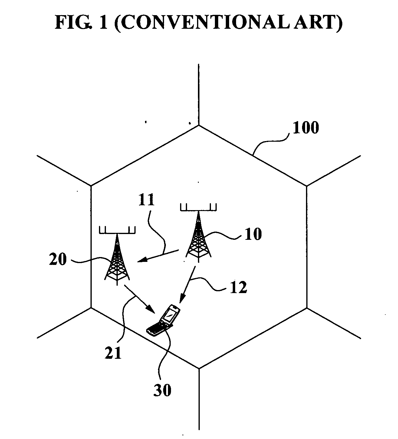
However, since a plurality of antennas cannot be installed in the MS due to a spatial restriction, there are some constraints to acquire an overall high multiplexing gain.
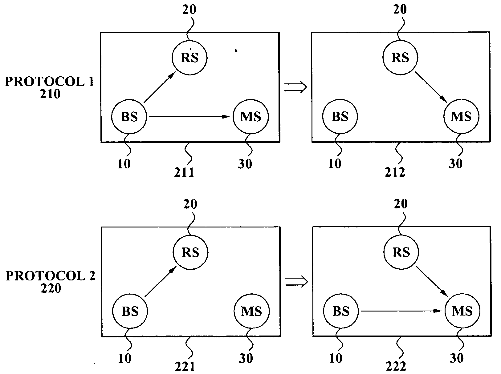
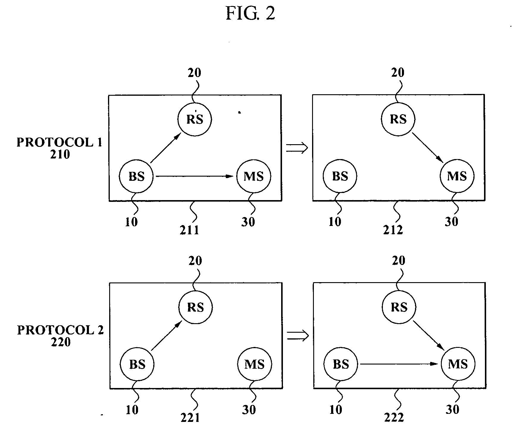
Also, some studies, which are based on the protocol 220 and usually focus only on how to increase a diversity gain, do not address a way to improve throughput.

Method used


Image

  • Method of controlling data transmission in a wireless relay system, and the relay system implementing the method
  • Method of controlling data transmission in a wireless relay system, and the relay system implementing the method
  • Method of controlling data transmission in a wireless relay system, and the relay system implementing the method

Examples


Embodiment Construction

[0043]Reference will now be made in detail to exemplary embodiments of the present invention, examples of which are illustrated in the accompanying drawings, wherein like reference numerals refer to the like elements throughout.

[0044]FIG. 3 illustrates operations of three transmission modes supported by a method of controlling a data transmission according to an exemplary embodiment of the present invention.

[0045]A first transmission mode illustrated in FIG. 3 indicates a direct transmission mode 310 where total data is directly transmitted from a base station (BS) 110 to a mobile station (MS) 130 while not passing through a relay station (RS) 120.

[0046]A second transmission mode illustrated in FIG. 3 indicates a diversity mode 320 where total data is directly transmitted from the BS 110 to the MS 130 and, at the same time, the identical total data is transmitted from the BS to the MS130 via the RS 120.

[0047]In a spatial multiplexing mode 330, a certain ratio α of total data is tran...


PUM


Abstract

A data transmission method in a wireless relay system, and a method of selecting an optimal transmission mode based on a channel capacity of an individual link that is measured by a mobile station. The data transmission method includes: transmitting a first ratio of first partial data of the data from a base station to a mobile station; transmitting a second ratio of second partial data of the data from the base station to a first relay station; and forwarding the second partial data from the first relay station to the mobile station, wherein the first ratio or the second ratio is determined based on any one of a channel capacity of a first link between the base station and the mobile station, and a channel capacity of a second link between the first relay station and the mobile station.

Description

CROSS-REFERENCE TO RELATED APPLICATION[0001]This application claims priority from Korean Patent Application No. 10-2006-0078940, filed on Aug. 21, 2006, in the Korean Intellectual Property Office, the entire disclosure of which is incorporated herein by reference.BACKGROUND OF THE INVENTION[0002]1. Field of the Invention[0003]Apparatuses and methods consistent with the present invention relate to a data transmission in a wireless relay system. More particularly, the present invention relates to a method of selecting an optimal transmission mode based on a channel capacity of an individual link that is measured by a mobile station.[0004]2. Description of Related Art[0005]Multiple In Multiple Out (MIMO) technology is currently being discussed in association with improving a performance of a mobile communication system. The MIMO technology designates a technology which installs a plurality of antennas in each of a base station (BS) and a mobile station (MS), and increases a high speed ...

Claims


Application Information

Patent Timeline
Patent Type & Authority Applications(United States)
IPC IPC(8): H04Q7/20H04W28/18H04W40/22
CPCH04W28/18H04W40/22H04L1/0668H04L1/0025H04L2001/0097
Inventor KIM, YOUNG-DOOKIM, EUNG SUNAHN, CHANG WOOKNAM, SEUNG HOON
Owner SAMSUNG ELECTRONICS CO LTD
Learn More