Accelerated Shells Trajectory MRI Acquisition

a three-dimensional, trajectory technology, applied in the field of mri methods and systems, can solve the problems of two relatively large “polar icecaps” at the poles of the shells that are left unsampled, and achieve the effects of shortening the tr and signal readout duration, and reducing the contribution of fat signal and other off-resonance effects

Active Publication Date: 2008-02-21
MAYO FOUND FOR MEDICAL EDUCATION & RES
View PDF3 Cites 10 Cited by
  • Summary
  • Abstract
  • Description
  • Claims
  • Application Information

AI Technical Summary

Benefits of technology

[0011]The present invention is a method for acquiring 3D MR image data using a series of shell sampling patterns. One aspect of the present invention enables a shorter TR and signal readout duration for the central shells by using a variable TR. This is particularly important because the central shells cover the central portion of k-space, which governs the low spatial frequencies and overall contrast of the images. Consequently, reducing the contribution of fat signal and other off-resonance effects by shortening the TR for the central shells has a disproportionately beneficial effect for reducing artifacts.
[0012]In the shells acquisition, the surfaces of the shells are covered with helical spiral k-space trajectories. In the proposed invention, readout duration and TR is reduced for the central shells by realizing that fewer sampling points are required to cover the surface of the smaller, central shells, while still satisfying the Nyquist criterion as shown in FIG. 2. Consequently, at a fixed receiver bandwidth, the readout duration for the innermost shells are also reduced. For example, if a total of 128 shells are required, one can acquire 256 complex k-space sample points per TR for each of the innermost 10 shells, and then increase to 512 complex sample points for each TR in shell numbers 11-128. In fact, even with 512 sample points per TR, multiple interleaves may be required to cover the larger shells as shown in FIG. 3. In this example, the TR for the innermost shells may be reduced, for example, to approximately 5 ms, while the TR for the outer shells may be 8 ms. The readout time is similarly reduced, for example, from 4 ms to 2 ms for the central shells assuming a typical readout bandwidth of ±64 kHz. The reduction of 3 ms in TR for this example helps suppress fat signals, and allows for higher spatial resolution during a CEMRA exam because there is more time to acquire high spatial frequency data when the contrast agent is still present in high concentration in the arteries of interest. The 2 ms reduction in readout time reduces off-resonance blurring from chemical shift and susceptibility variation simply because there is less time for the off-resonance spins to accumulate phase.
[0013]Another aspect of the present invention is a variation in the shells sampling trajectory to aid in the acquisition of larger shells at the periphery of k-space. As shown in FIG. 6, as the shells get larger, it becomes more difficult to cover the “polar icecap” regions 6 and 8 of the shell 9 due to slew rate restrictions on the gradient hardware, and associated peripheral nerve stimulation of the patient due to rapidly changing gradient fields. Covering of the equatorial region of the shell up to latitudes of approximately ±45°, does not place as strict requirements on the gradient hardware. However, two relatively large “polar icecaps” at the poles of the shell are left unsampled. This problem is solved by using two or more overlapping equatorial shell acquisitions 11 and 13 having the same radius, but with their central axes 15 and 17 tilted relative to each other, as illustrated in FIG. 7. A preferred method is for the axes of the two helical spiral shells to be tilted relative to each other by 90°. The two equatorial shell acquisitions therefore sample each other's unsampled polar “icecap” parts. As a result, the polar icecap regions need not be sampled by additional helical spiral interleaves. In this way, the slew rate problems associated with acquiring data at the “polar latitudes” is avoided. The overlapped parts of the two tilted interleaves will sample k-space at higher sampling rate than the rest of the shells, and the increased sampling can be used to either improve SNR, or reduce undersampling artifacts if the shell is designed to be undersampled.

Problems solved by technology

However, two relatively large “polar icecaps” at the poles of the shell are left unsampled.

Method used


Image

  • Accelerated Shells Trajectory MRI Acquisition
  • Accelerated Shells Trajectory MRI Acquisition
  • Accelerated Shells Trajectory MRI Acquisition

Examples


Embodiment Construction

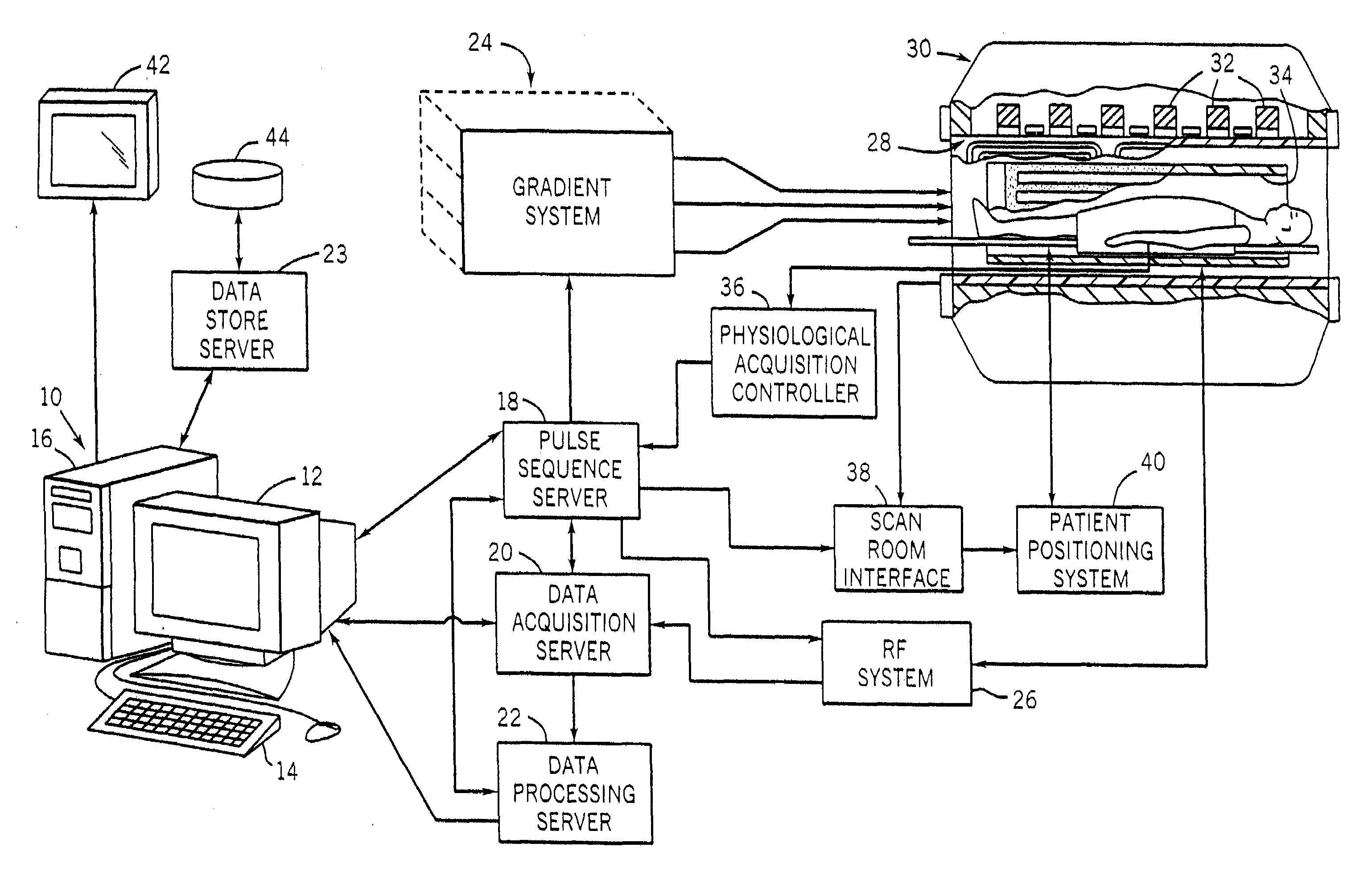
[0021]Referring particularly to FIG. 1, the preferred embodiment of the invention is employed in an MRI system. The MRI system includes a workstation 10 having a display 12 and a keyboard 14. The workstation 10 includes a processor 16 which is a commercially available programmable machine running a commercially available operating system. The workstation 10 provides the operator interface which enables scan prescriptions to be entered into the MRI system.

[0022]The workstation 10 is coupled to four servers: a pulse sequence server 18; a data acquisition server 20; a data processing server 22, and a data store server 23. In the preferred embodiment the data store server 23 is performed by the workstation processor 16 and associated disc drive interface circuitry. The remaining three servers 18, 20 and 22 are performed by separate processors mounted in a single enclosure and interconnected using a 64-bit backplane bus. The pulse sequence server 18 employs a commercially available micro...


PUM


Abstract

An MRI k-space data set is acquired using a series of shell k-space sampling trajectories of different radii. Off-resonance effects are reduced and fat-suppression can be improved by using a shorter TR for pulse sequences that sample at smaller radii. At larger radii sampling is repeated with the central axis of the shell sampling trajectory tilted such that the polar regions of shells acquired at the same radii are sampled by the other shell.

Description

CROSS-REFERENCE TO RELATED APPLICATIONS[0001]This application is based on U.S. Provisional Patent Application Ser. No. 60 / 837,704 filed on Aug. 15, 2006 and entitled “ACCELERATED SHELL TRAJECTORY MRI ACQUISITION.”BACKGROUND OF THE INVENTION[0002]The field of the invention is nuclear magnetic resonance imaging (MRI) methods and systems. More particularly, the invention relates to the rapid acquisition of three-dimensional MR images using a shells sampling trajectory.[0003]Any nucleus that possesses a magnetic moment attempts to align itself with the direction of the magnetic field in which it is located. In doing so, however, the nucleus precesses around this direction at a characteristic angular frequency (Larmor frequency) which is dependent on the strength of the magnetic field and on the properties of the specific nuclear species (the magnetogyric constant γ of the nucleus). Nuclei which exhibit this phenomena are referred to herein as “spins”.[0004]When a substance such as human...

Claims


Application Information

Patent Timeline
Patent Type & Authority Applications(United States)
IPC IPC(8): A61B5/055
CPCG01R33/4824G01R33/5635G01R33/561
Inventor SHU, YUNHONGBERNSTEIN, MATTHEW
Owner MAYO FOUND FOR MEDICAL EDUCATION & RES
Why Eureka
Try Eureka