
Composite Anchor Bolt and Method for Installation

a technology of anchor bolts and composite anchors, applied in the direction of building components, building repairs, foundation engineering, etc., can solve the problems of anchor bolt damage, concrete reinforcement, and inability to install post-construction anchor bolts, and achieve high load resistance functions, ensure the design strength of the building structure, and reinforce the margin.

Active Publication Date: 2008-02-28
SUEHIRO SYST CO LTD
View PDF8 Cites 2 Cited by
  • Summary
  • Abstract
  • Description
  • Claims
  • Application Information

AI Technical Summary

Benefits of technology

[0010]The composite anchor of the present invention comprises a first anchor bolt installed projecting outside of a concrete frame; a second anchor bolt which is positioned eccentrically to the axis of said first anchor bolt; and a connecting part for connecting said first and second anchor bolts, characterized in that said connecting part is provided with projecting portion which projects in the opposite direction to the first anchor bolt, and thus reduces the bending moment which is exerted locally on the connecting part due to a load on said first anchor bolt.
[0013]In this construction, the connecting part is formed in either a cylindrical, triangular, quadrangular or polygonal shape to increase its surface area, so that it is possible to increase the adhering area of the composite anchor with the concrete. Also, it is preferably constructed with additional reinforcing portion which resist against the bending moment exerting locally on the joining point between said second anchor bolt and connecting part. Also, said first anchor bolt and said second anchor bolt are preferably formed with similar or different diameters. Said second anchor bolt may have a larger diameter than said first anchor bolt, and is preferably formed with a shorter length in the embedded concrete. Furthermore, said connecting part can provide an injection hole for an adhesive and air hole, and at least one of said first anchor bolt and second anchor bolt can be removably attached to said connecting part.
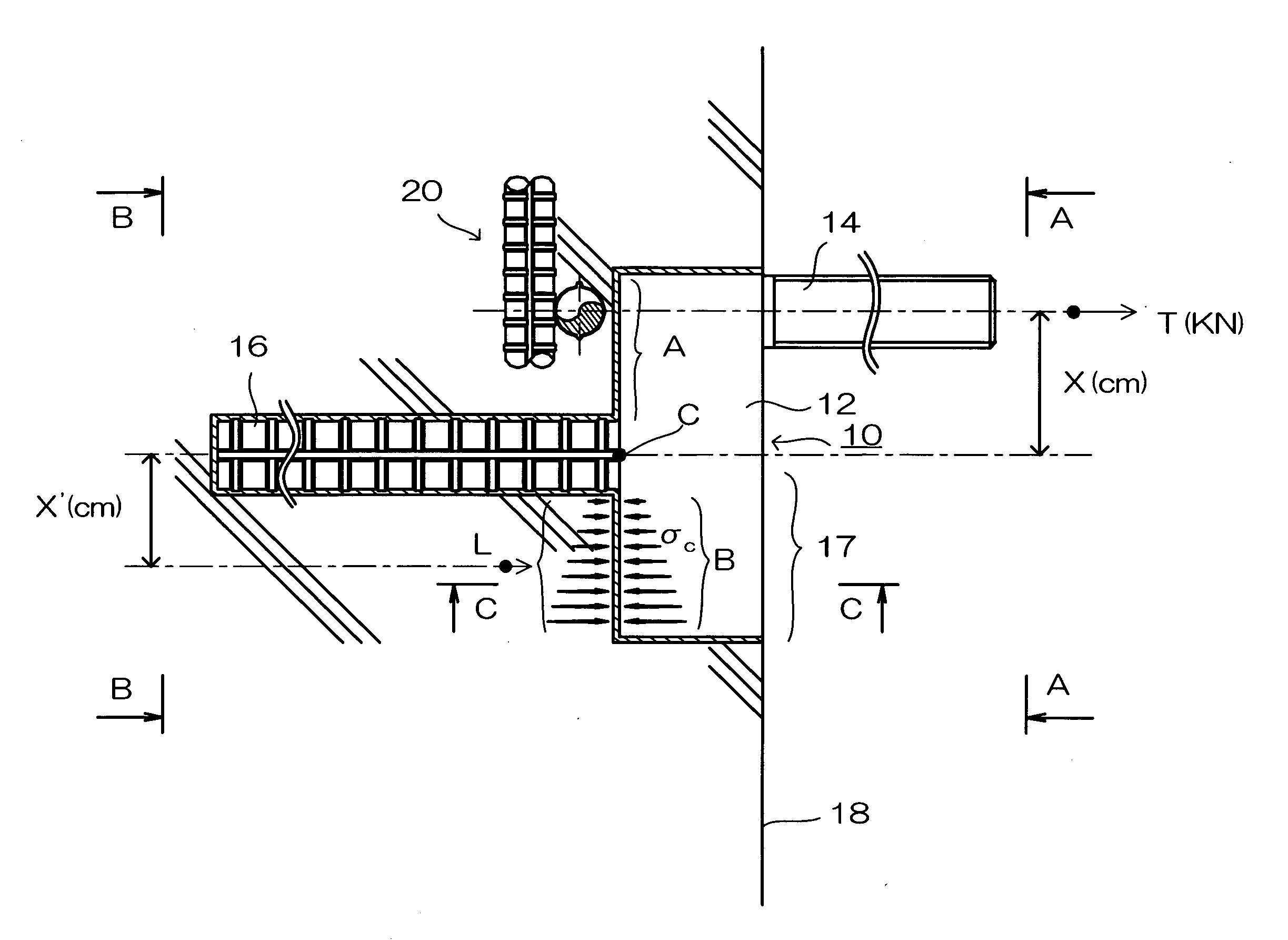
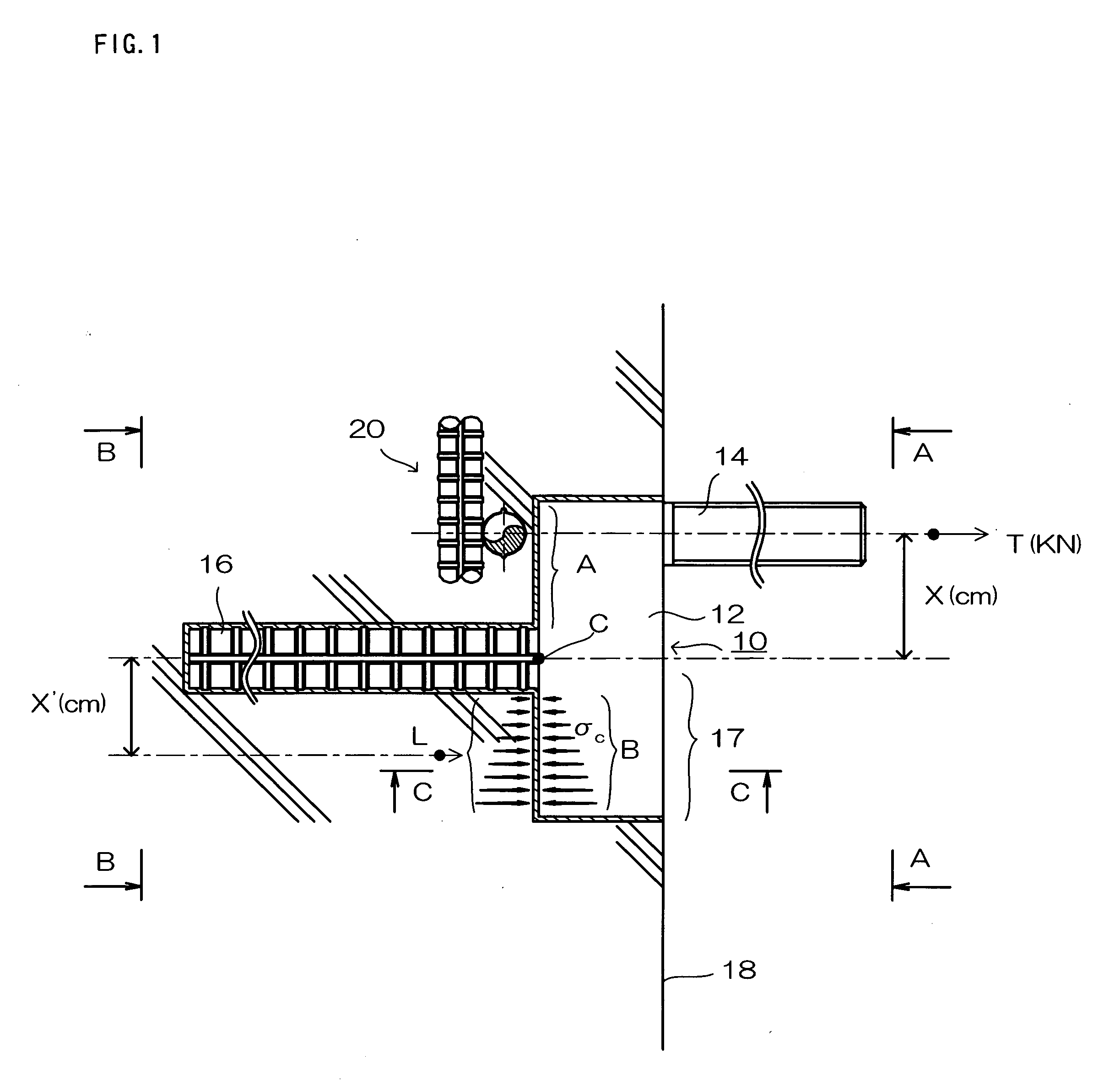
[0018]According to the composite anchor bolt of the present invention, there is a force acting on the joining portion of the connecting part and the second anchor bolt caused by a bending moment which occurs due to the tensile force acting upon the first anchor bolt, the projecting portion of the connecting part acts to generate compressive force on the concrete frame, the force occurring due to this provides resistance to the bending force, thus in the connecting part of the composite anchor bolt, the bending moment acting on the second anchor bolt according to the ‘lever’ principle is reduced. Therefore, even if the reinforcement covering margin is limited, it is possible to provide a large size of composite anchor bolt with high load resistance function.
[0019]Furthermore, previously, when reinforcement is encountered, bad construction practices are commonly used such as the cutting of reinforcement and using anchor bolts of incorrect length. However, the composite anchor bolt of the present invention provides for proper installation without interfering with the reinforcement in the concrete frame, therefore guaranteeing the design strength of the building structure.
[0020]Furthermore, in prior methods of installation, the frame is cut until the reinforcement is exposed, the anchor bolt is then welded, the frame is filled with concrete, and the concrete is cured until hard to complete the installation. In the composite anchor bolt of present invention, cutting, welding, concrete filling, and cutting waste disposal operations are all unnecessary. This reduces the emission of environmental indicator CO2, reduces labor, and enables the planning of shorter construction times because the curing period is significantly shorter.

Problems solved by technology

The greatest problem experienced in the installation of conventional post construction anchor bolts is the existence of reinforcement in the concrete.
It is not possible to install a post-construction anchor bolt if the anchor bolt borehole encounters reinforcement.
Therefore, problems can occur, such as bending at the joining point of the connecting part and the anchor bolt (embedded in the concrete), which is caused by an excessive bending moment exerting force on the connecting part Specifically, if tensile force T(KN) acts on the first anchor bolt 2, point C does not shift because of an adequate tensile force between the second anchor bolt and frame, but a bending moment of T×x(KN·cm) does act on point C. If this bending moment increases, joining point C of connecting part 1 and second anchor bolt 3 will bend, therefore damaging the anchor bolt.
Consequently, the use of the traditional type of anchor bolt cannot be adopted by scale-up only.

Method used


Image

  • Composite Anchor Bolt and Method for Installation
  • Composite Anchor Bolt and Method for Installation
  • Composite Anchor Bolt and Method for Installation

Examples


first embodiment

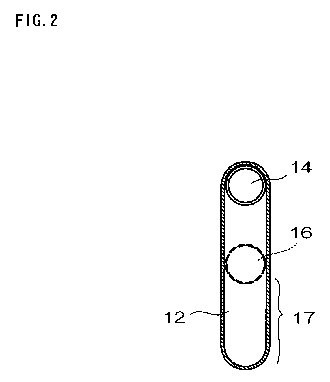
[0040]The best mode of the composite anchor bolt of the present invention and the method for its installation will be described in detail, referring to the accompanied drawings. FIG. 1 shows the side view of the T-shaped composite anchor bolt according to the present invention. FIG. 2 shows a view taken in the direction of the arrows A-A in FIG. 1. FIG. 3 shows a view taken in the direction of the arrows B-B in FIG. 1. FIG. 4 shows a cross-sectional view taken along the line C-C of FIG. 1.

[0041]The composite anchor bolt of the present embodiment is post-constructed into a concrete frame. It comprises a first anchor bolt installed projecting from outside of the concrete frame, and a second anchor bolt positioned eccentrically to the axis of said first anchor bolt, and a connecting part installed embedded in the concrete frame together with said second anchor bolt. On the said connecting part, a projecting portion is formed in the opposite direction to the first anchor bolt, and the p...

second embodiment

[0055]FIG. 7 is an explanatory drawing of the circular type of composite anchor bolt according to the FIG. 7 is a side view of the anchor bolt set inside of concrete frame 218. FIG. 8 shows a view taken in the direction of the arrows A-A in FIG. 7. FIG. 9 shows a view of taken in the direction of the arrows B-B in FIG. 7.

[0056]210 in the figure denotes the large, circular type of the composite anchor bolt in the second embodiment. In the present embodiment, a circular or planar connecting part 12 is used in place of the connecting part 12 having oblong surface in the aforementioned T-shaped composite anchor bolt. This point distinguishes the second embodiment from the first embodiment.

[0057]214 in the figure denotes the first anchor bolt, and extending along its axis is reinforcement frame 220. In short, during borehole drilling for installation of a normal anchor in concrete frame 218, reinforcement frame 220 is encountered, therefore a circular type of composite anchor bolt is us...

third embodiment

[0073]The method of installation for the composite anchor bolt in the third embodiment can be carried out as follows.

[0074]In the prior art composite anchor bolt, a first anchor bolt borehole is drilled, and a second anchor bolt borehole is then drilled positioned away from the first borehole by x.

[0075]In the installation of the circular type of composite anchor bolt 310, when reinforcement is encountered when drilling a borehole for the first anchor bolt, a core is removed of the diameter φP×depth H on the same axis. Next, the arrangement of the reinforcement is confirmed, and a borehole is drilled for the second anchor bolt at a point where reinforcement does not exist. An adhesive capsule is then injected and the circular type of composite anchor bolt 310 is installed. Following this, adhesive is injected through adhesive injection port 324. Lastly, the adhesive is left to cure to complete the installation.

[0076]The installation for the circular type composite anchor bolt 310 ca...


PUM


Abstract

A post-construction composite anchor bolt is provided having great resistance to a bending moment, even when the reinforcement covering margin is small, and reduces the transformation force caused by the bending moment acting on the joining point between the connecting part and the second anchor bolt, even if the size of the anchor bolt is increased. A post construction anchor bolt in the concrete frame comprising: a first anchor bolt installed projecting outside of a concrete frame; and a second anchor bolt which is eccentrically positioned to the axis of said first anchor bolt and is installed embedded in the concrete frame, and a connecting part which links said first anchor bolt and said second anchor bolt, and is installed embedded in the concrete frame together with said second anchor bolt. Said connecting part is formed to have a portion projecting in the opposite direction to the first anchor bolt, and thus reduces the bending moment which is exerted locally on the connecting part due to the load on said first anchor bolt.

Description

BACKGROUND OF THE INVENTION[0001]1. Field of the Invention[0002]The invention relates to a ‘post-construction’ anchor-bolt which is installed into the floor, wall or ceiling after a reinforced concrete frame is matured.[0003]2. Description of the Related Art[0004]Prior post-construction anchor bolts are classified into adhesive anchors and driving anchors (metal-formed extendable anchors), which each consist of various types. In the installation of a post construction adhesive anchor, a capsule filled with adhesive or adhesive itself is embedded into a borehole which has been drilled in advance in a concrete frame, the anchor bolt is inserted, and when the adhesive cures, the concrete and anchor bolt fasten together to complete the installation.[0005]The greatest problem experienced in the installation of conventional post construction anchor bolts is the existence of reinforcement in the concrete. It is not possible to install a post-construction anchor bolt if the anchor bolt bore...

Claims


Application Information

Patent Timeline
IPC IPC(8): E04B1/38
CPCE04B1/4157
Inventor SUEHIRO, MORIOSUEHIRO, HIROKAZU
Owner SUEHIRO SYST CO LTD
Learn More