Heat recovery system

a heat recovery and seawater technology, applied in the direction of gas handling/storage effect, fluid transfer, container discharging method, etc., can solve the problem of large quantities of seawater used as heat source for vaporisation of lng, need to generate electrical power, and other equipment still require a significant amount of cooling, so as to achieve the effect of easy replenishmen

Inactive Publication Date: 2008-02-28
BHP BILLITON INNOVATION PTY LTD
View PDF0 Cites 92 Cited by
  • Summary
  • Abstract
  • Description
  • Claims
  • Application Information

AI Technical Summary

Benefits of technology

[0035]In the above embodiments, the intermediate heat exchange fluid is preferably water, most preferably water with additives, such as corrosion inhibitors and / or glycols. If desired, the intermediate heat exchange fluid may include seawater, so that it can easily be replenished, when necessary.

Problems solved by technology

The use of large quantities of seawater as a heat source for vaporisation of LNG has now been recognised as a problem in many locations due to the environmental effect of thermal discharges, chemical emissions and destruction of marine organisms.
Facilities using these alternatives however, still need to generate electrical power to run the regasification process.
These power generation facilities and other equipment still require a significant amount of cooling and this would normally be supplied from a standard marine system using seawater as the cooling medium.
Due to the large power requirements for these facilities the amount of seawater required can still be significant and also raises environmental concerns due to the thermal and chemical discharges and destruction of fish larvae and eggs in the intake systems.
This increases the size and power requirements of the cooling water equipment and also will increase the amount of marine organisms ingested into the intake.

Method used


Image

  • Heat recovery system
  • Heat recovery system
  • Heat recovery system

Examples


Embodiment Construction

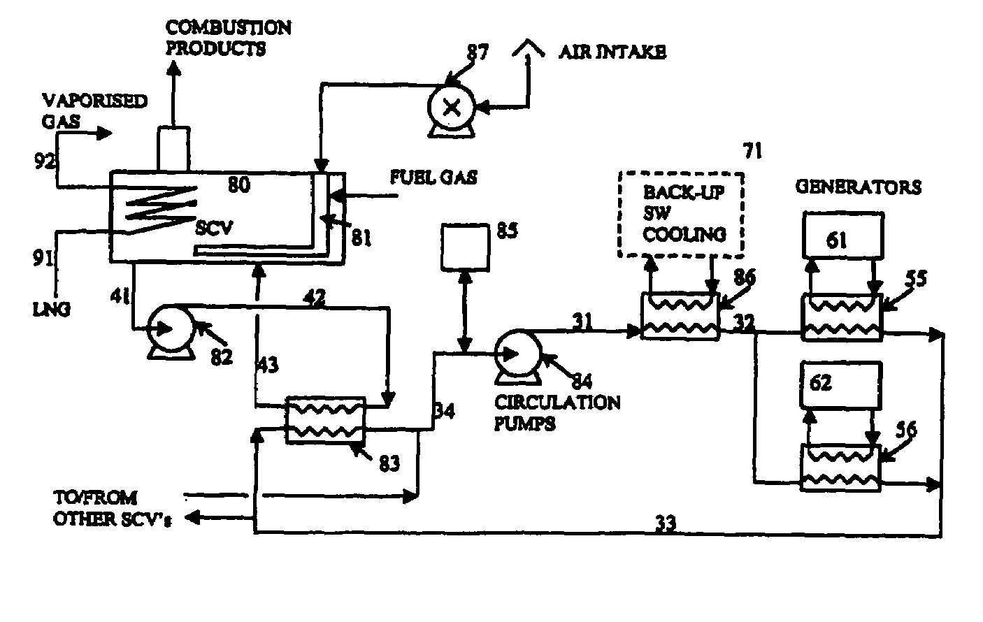
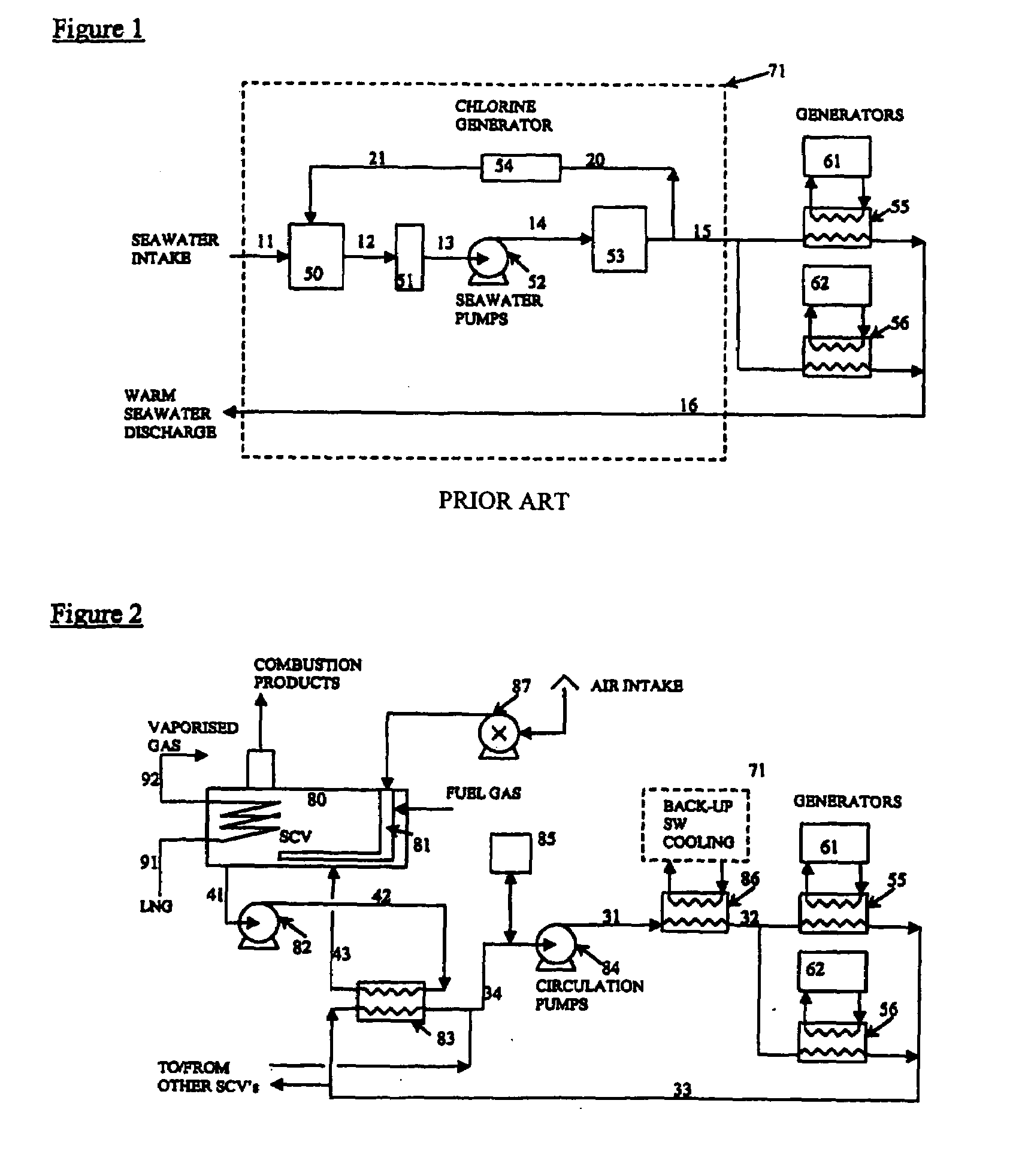
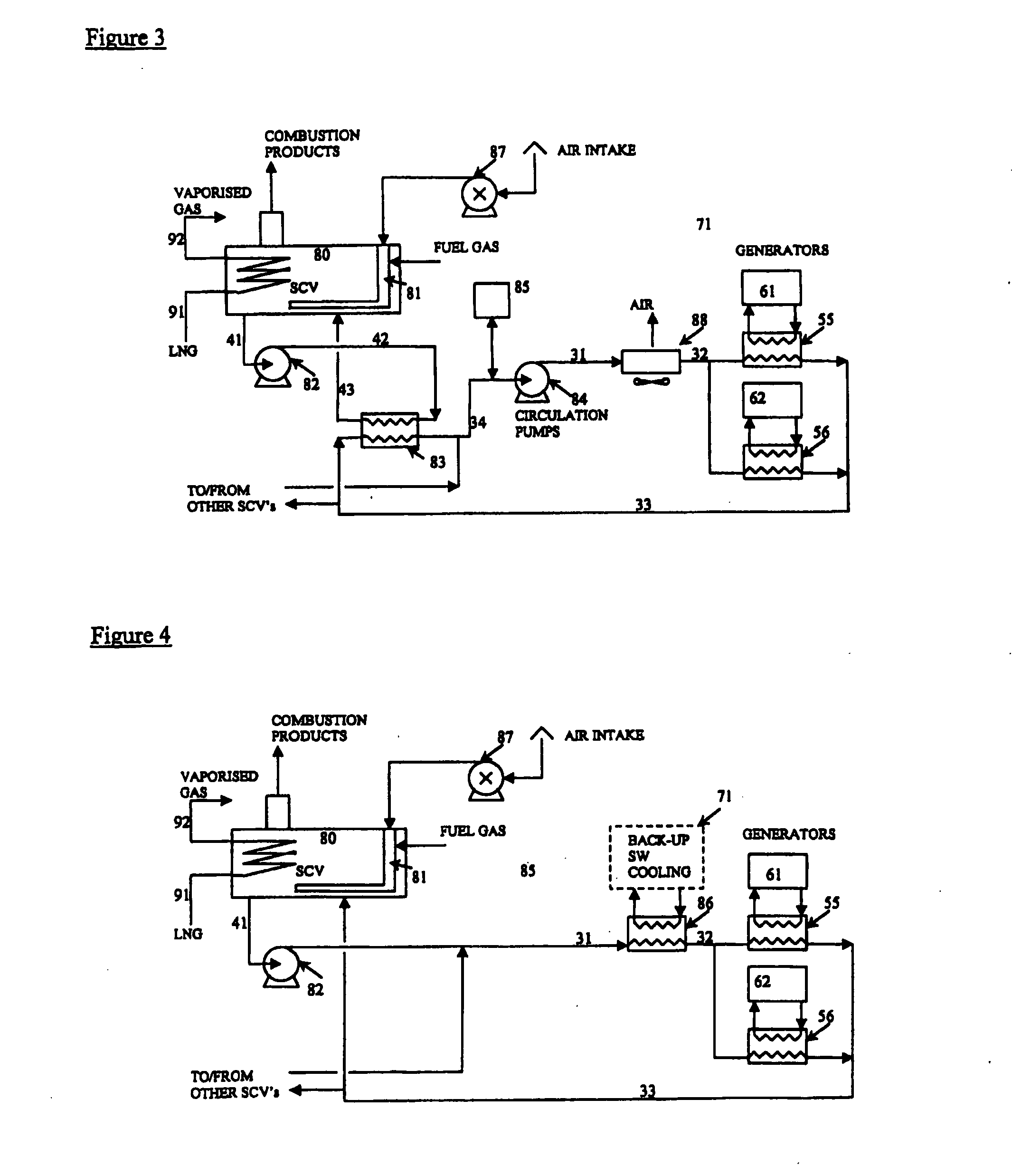
[0045]LNG is pumped from storage (91) and passed through coils submerged in a water bath (80) and is vaporised by heat exchange with the water in the bath. The water in the bath is heated and agitated to ensure good heat transfer by the combustion gases produced in a submerged combustion burner (81). Air is supplied from a blower (87) and fuel is supplied from the boil-off gas from the LNG storage tanks and / or part of the vaporised LNG. The combustion products leave the water bath at close to the water bath temperature and so the process has a very high thermal efficiency although the use of vaporised gas (typically 1.5% of LNG throughput) incurs a high operating cost. The combustion products are also a source of greenhouse gases and contain some NOx pollutants.

[0046]In this invention the SCV water bath is used as a heat sink to provide cooling for the engine room generators and auxiliary equipment. The primary purpose of the invention is to eliminate the intake of cooling water dur...


PUM


Abstract

A heat recovery system comprising: an LNG warmer; at least one item of equipment requiring cooling and thereby generating waste heat; a heat exchanger arranged to provide heat exchange between the LNG warmer and the waste heat, whereby said waste heat can be used to provide warming for the LNG; wherein said heat exchanger is a closed loop heat exchange means, whereby the heat exchange fluids in said heat exchanger are substantially retained within the heat exchanger during operation of the system. This enables the system to be operated offshore without needing to use the surrounding seawater to provide cooling for the waste heat from the equipment.

Description

[0001]This invention relates to a heat recovery system. More particularly, the invention relates to an offshore heat recovery system which reduces or even substantially eliminates the need to use external seawater for cooling. The invention also relates to a method of warming Liquefied Natural Gas (LNG).BACKGROUND TO THE INVENTION[0002]Offshore LNG import terminals are being considered in many coastal locations and the design for some of these facilities involves a Floating Storage and Regasification Unit (FSRU). Other regasification facilities have been proposed on fixed gravity based structures (GBS) or other offshore structures. The use of large quantities of seawater as a heat source for vaporisation of LNG has now been recognised as a problem in many locations due to the environmental effect of thermal discharges, chemical emissions and destruction of marine organisms. The use of submerged combustion vaporisers (SCV) or ambient air vaporisers are alternative regasification meth...

Claims


Application Information

Patent Timeline
Patent Type & Authority Applications(United States)
IPC IPC(8): F17C9/02
CPCF17C9/02F17C2221/033F17C2223/0161F17C2223/033F17C2265/05F17C2225/035F17C2227/0323F17C2227/0332F17C2227/0393F17C2225/0123
Inventor DUBAR, CHRISTOPHER ALFRED TIMOTHY
Owner BHP BILLITON INNOVATION PTY LTD
Why Eureka
Try Eureka