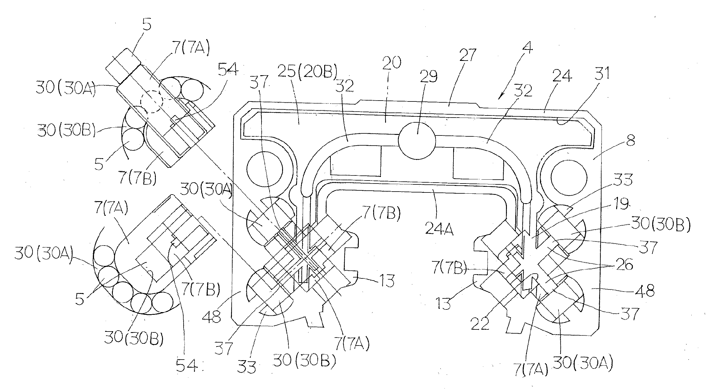
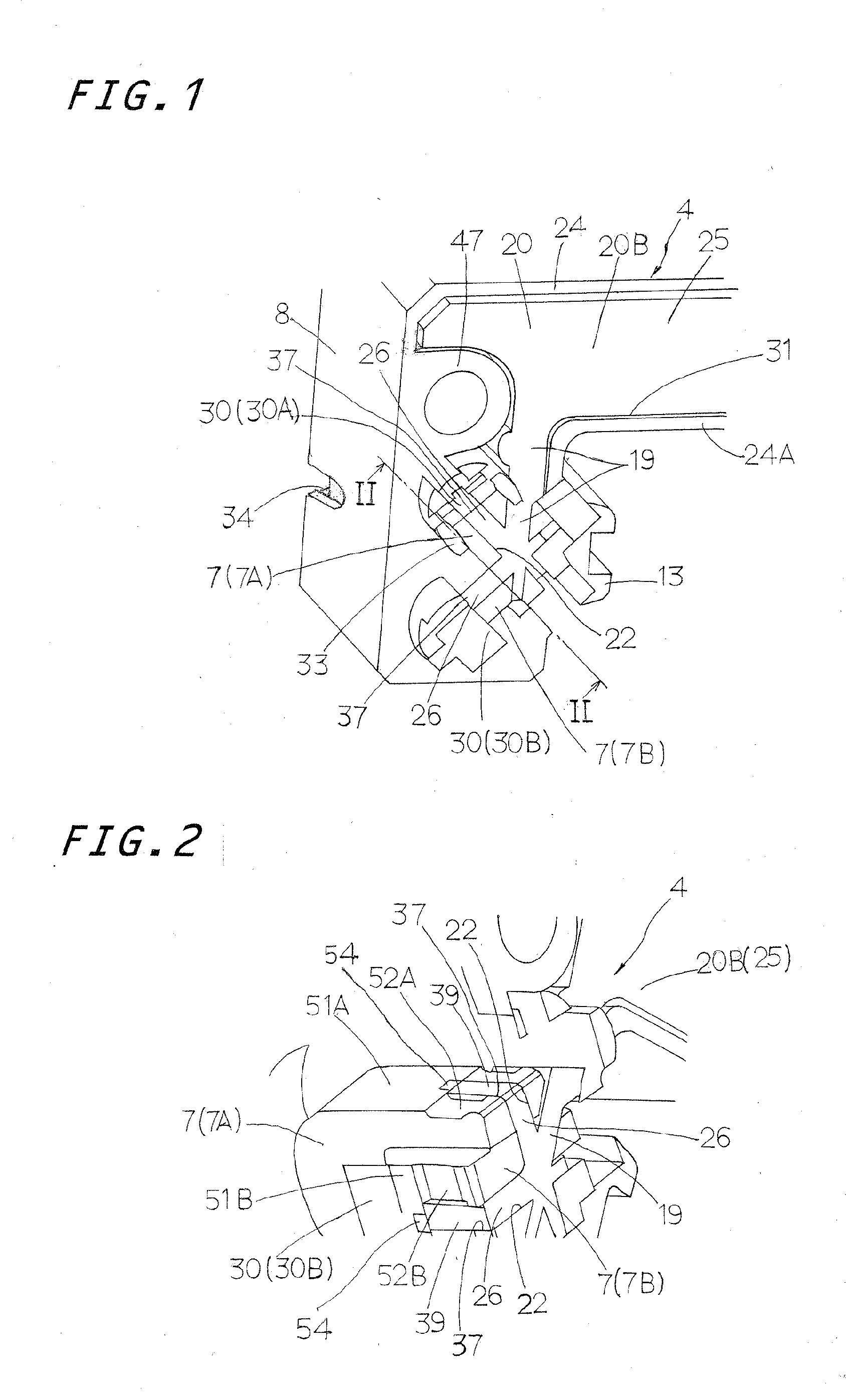
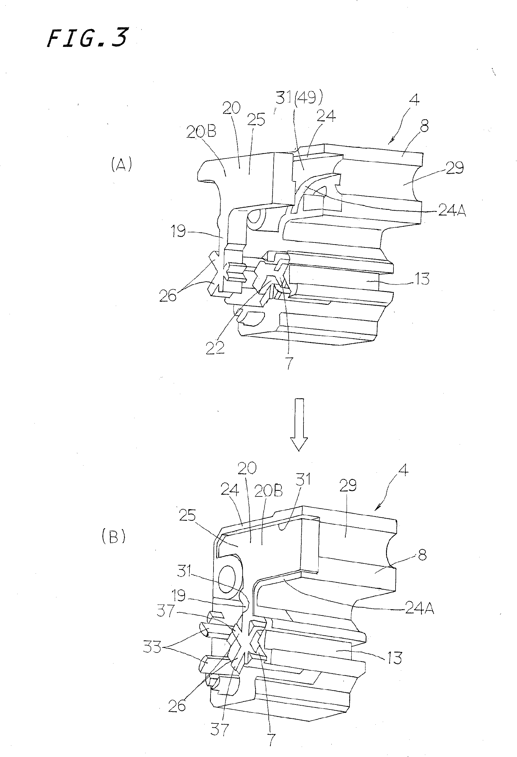
[0007]The present invention has for its primary object to overcome the major challenges as stated earlier, and to provide a linear motion guide unit adapted to be used in a reciprocating mechanism built in
semiconductor fabricating equipment,
machine tools, industrial robots, and so on. The linear motion guide unit employs rollers as rolling element and further uses a binding strip to fasten for example a
retainer plate to keep the rollers against falling away from a slider. More particularly, the present invention is envisaged coping with lack of space for a lubrication
system chiefly because grooves to fit over the binding strip is
cut into an outward end surface of an end cap, which is in the face of the associated end seal. To this end, the present invention provides a linear motion guide unit in which an end cap has a concavity on an inward end surface thereof which faces directly towards a
carriage of the slider, and a cellular or porous compact impregnated with lubricant fits into the concavity, the end cap being constituted with an end cap major body and a spacer part to be nested inside the end cap major body, and the spacer part having a hole open to a turnaround passage. With the linear motion guide unit constructed according to the present invention, application of lubricant on the rollers can be done by only a simplified lubrication
system. Moreover, the porous compact, as adapted to conform to the deep concavity in the end cap, is allowed to have a lubricant reservoir capable of retaining lubricant therein as large in volume as possible. Even if the end cap is small in construction, the porous compact itself can have the lubricant reservoir which is impregnated with ample lubricant enough to conduct steady and sustainable application of lubricant around the rollers with accompanying maintenance-free lubrication over a long-lasting period.
[0018]In the present invention, there is disclosed a linear motion guide unit suited for the construction in which the end cap major body has an outward end surface facing directly to an end seal, the outward end surface having notches thereon to fit over bent ends of a binding strip which fastens a
retainer plate to the slider, the
retainer plate being installed to keep in place the rollers during their rolling throughout the load-carrying races and further keep the rollers against falling away from the slider after the slider has taken away from the guide rail.
[0019]The linear motion guide unit constructed as stated earlier according to the present invention is best suited, where the installation of the porous compact on the outward end surface of the end cap facing towards the end seal is impracticable, due to the lack of space for the porous compact, as in the end cap on whose outward end surface there is
cut notches or grooves to catch the ends of the binding strips. The porous compact impregnated with lubricant is fitted into the concavity which is made on the inward end surface of the end cap facing directly towards the end surface of the
carriage. The porous compact is designed to get exposed in part to the turnaround passages through the openings in the spacer parts assembled into the end caps. The rolling elements rolling through the turnaround passages, as coming into rolling-contact with at least one of the exposed parts of the porous compact, are applied with the lubricant. Thus, the lubrication system designed as stated earlier, even though simple in construction and easy in assemblage, is suited to conduct steady and sustainable application of lubricant around the rollers with accompanying maintenance-free lubrication over a long-lasting period.
[0020]With the linear motion guide unit of the present invention, moreover, there is no need of the porous compacts on both the forward and aft end caps. Instead, only the porous compact on any one of the forward and aft end caps is sufficient to apply the lubricant to all the load-carrying races in four-
line array. This alternative is effective in
cost savings and, upon replenishment of lubricant, is sufficient at only any one of the end caps rather than at both the forward and aft end caps.
[0021]In contrast, when the linear motion guide unit is required working under severe conditions as in high-tact performance, the porous compact impregnated with lubricant may be used in both the forward and aft end caps to increase the amount of lubricant applied around the rollers, thereby avoiding seizure or seize-up of the rolling elements due to oil starvation. Moreover, the porous compact after having fitted into the concavity in the end cap major body covers the oiling paths to seal oiling routes, keeping the lubricant against leakage. The lubricant flows through the oiling paths into the circulating circuits with seeping in the porous compact and, therefore, the porous compact can be easily replenished with the lubricant.
[0022]With the linear motion guide unit of the present invention, the porous compact has the major reservoir which is placed in the upper area out of the turnaround passages in the end caps to make sure of the volume as large as possible. A plenty of lubricant preserved in the major reservoir is led to the tips exposed to the turnaround passages, where the rolling elements come into rolling-contact with the tips and coated with the lubricant. Despite very simple construction, the lubrication system recited earlier helps steady and positive application of the lubricant around the rolling elements with steady with maintenance-free operation for lubrication over a prolonged service life.


