
Low fuel shut off for a portable welder generator

Inactive Publication Date: 2008-02-28
ILLINOIS TOOL WORKS INC
View PDF8 Cites 23 Cited by
  • Summary
  • Abstract
  • Description
  • Claims
  • Application Information

AI Technical Summary

Problems solved by technology

One issue with using a diesel engine in this application is the difficulty in restarting the engine after the fuel supply has been completely depleted, also known as running the engine dry.
The difficulty can be attributed to the difference in the combustion cycle of a diesel engine versus a gasoline engine.
The result is the air to fuel mixture becomes imbalanced, thereby inhibiting the combustion process and preventing the diesel engine from starting.
In addition, the higher compression ratio of the diesel engine provides significantly more engine braking than does a gasoline engine, thus making the engine even more difficult to initially crank.
Therefore, the imbalance in the air to fuel mixture makes starting the engines very difficult and results in excessive cranking of the engine.
Excessive cranking is undesirable because it can damage the ignition and starting system and other engine components.
Many diesel engines, once run dry, require performing the laborious task of bleeding the fuel line and injectors before the engine can be restarted.
This can be a time consuming operation, and requires that the operator know exactly how to perform it.
Furthermore, access to these components is often limited by an enclosure, making the task even more time-consuming and difficult to perform.
In welding applications, the operator may not be able to monitor the fuel level, particularly insomuch as the operator is rarely close to the power supply, and may work for extended periods as some distance, that is, at the location of the work piece.
Moreover, the welding operator clearly must carefully focus on the welding operation, and may not be able to direct sufficient attention to such issues as the engine fuel supply level.
There is an inherently increased risk of running a diesel engine dry in such situations.

Method used


Image

  • Low fuel shut off for a portable welder generator
  • Low fuel shut off for a portable welder generator
  • Low fuel shut off for a portable welder generator

Examples


Embodiment Construction

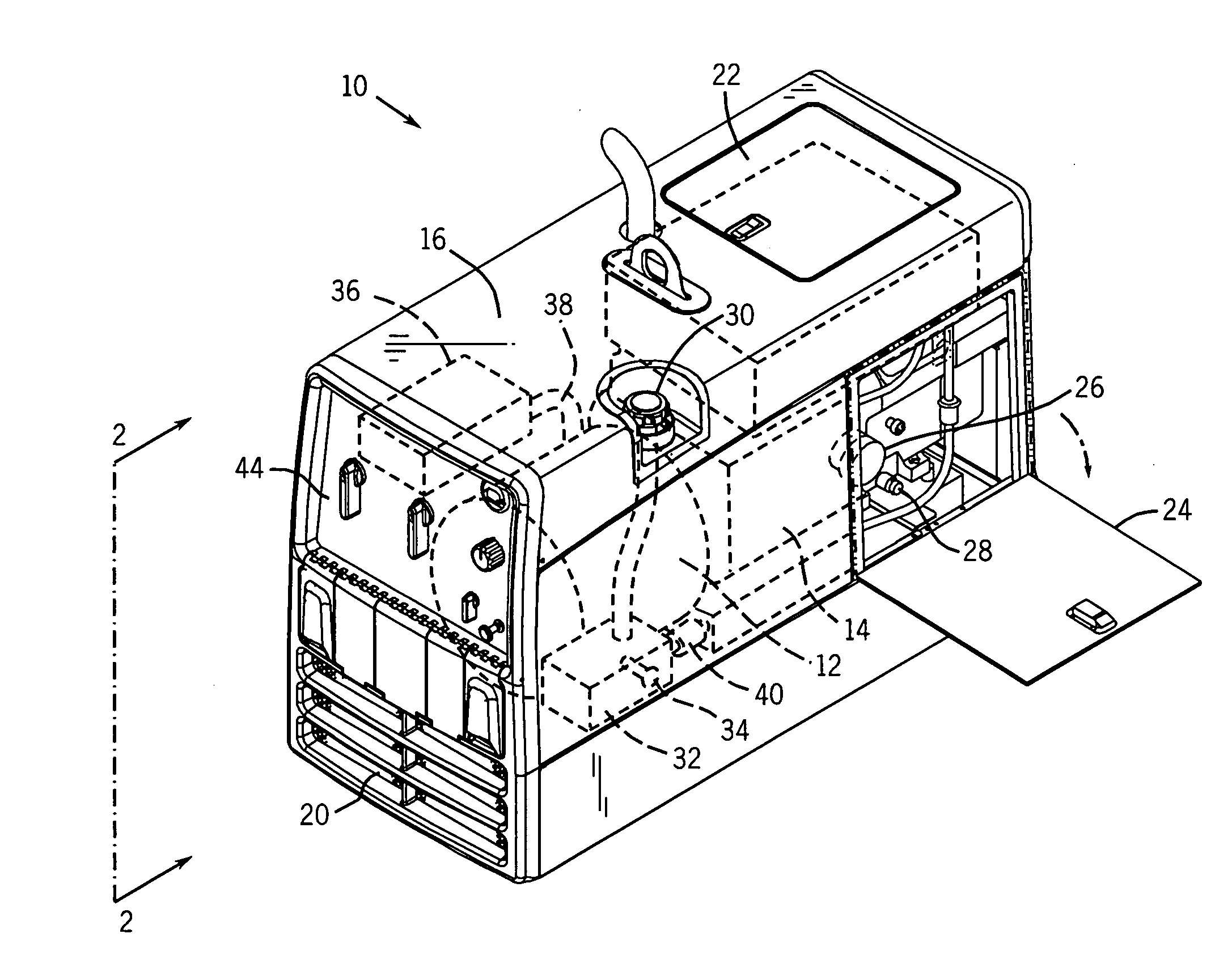
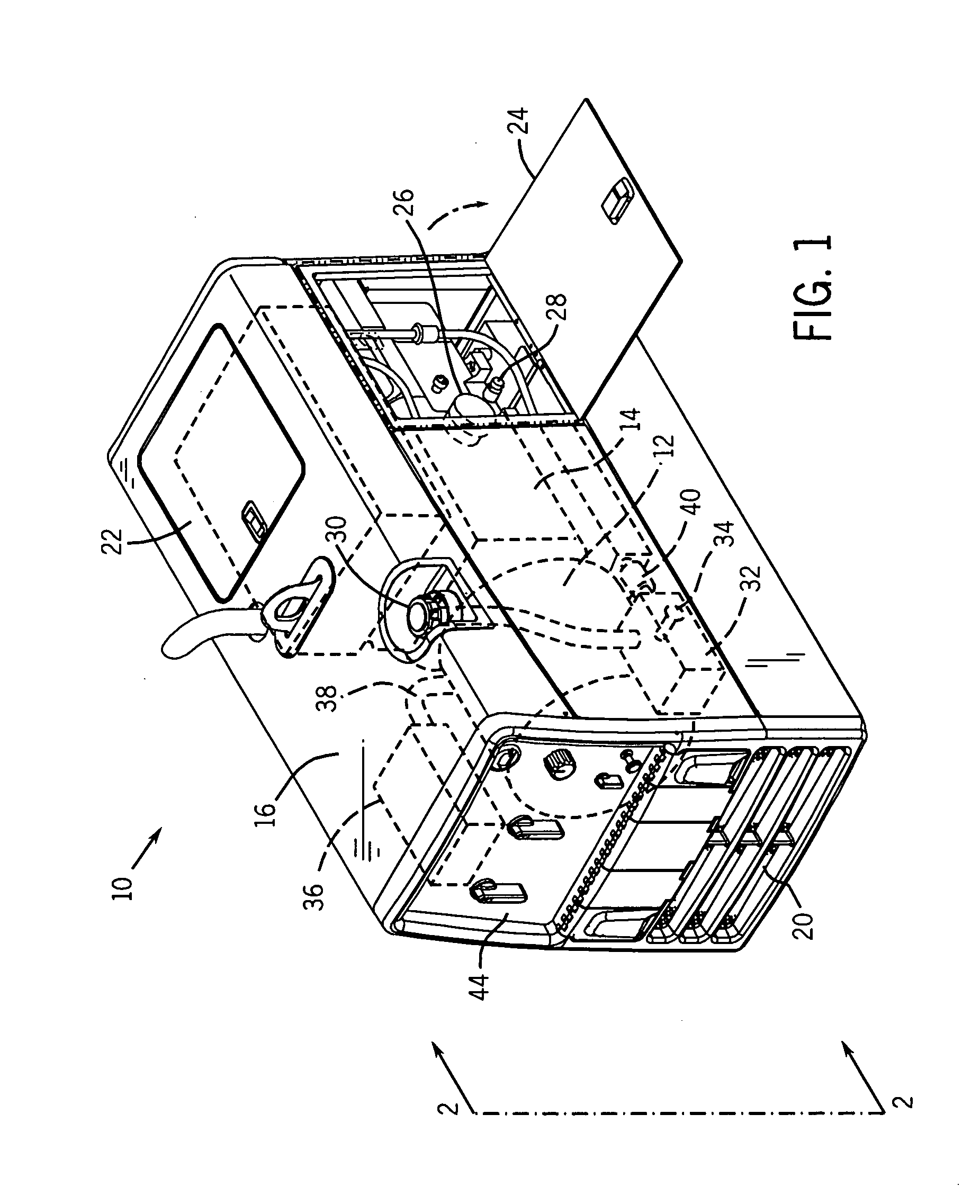
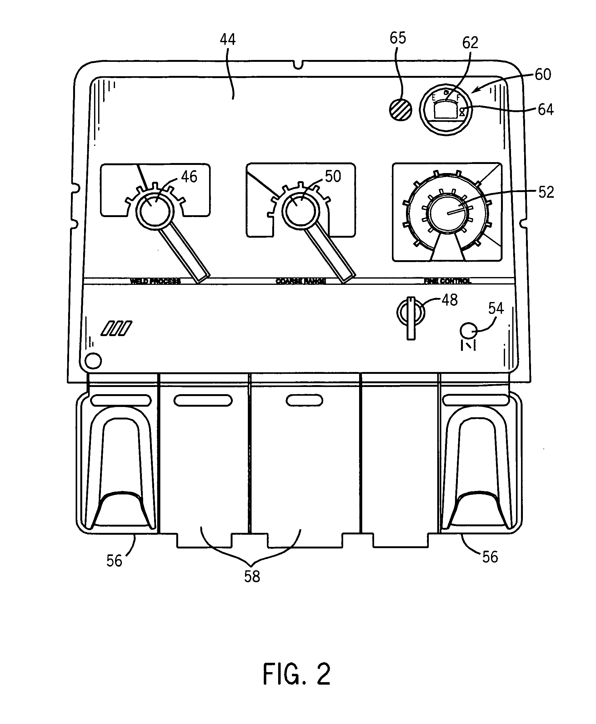
[0013]Turning now to the drawings, FIG. 1 illustrates the location of the respective elements of an exemplary engine-driven welder. The engine-driven welder 10 includes an electrical power generator 12 that is coupled to and driven by an engine 14. In the illustrated embodiment, the engine is a diesel engine. The engine and generator are fully enclosed by an enclosure 16. The enclosure protects the engine and generator form dust, debris, and so forth. The enclosure also reduces noise and helps to cool the engine by preventing hot air recirculation via the cool air inlet 20 pulling air through the interior volume of the enclosure. The enclosure incorporates panels allowing the operator to access the engine. A top panel 22 provides access to the top of the engine and allows the operator to perform such maintenance tasks as adding coolant. A side panel 24 allows the user to access the side of the engine where the oil filter 26 and oil drain 28 are located. Even though the panels do pro...


PUM

PropertyMeasurementUnit
Poweraaaaaaaaaa
Flow rateaaaaaaaaaa
Levelaaaaaaaaaa

Abstract

A low fuel shut off for a portable engine-driven welder is disclosed that disables the engine when the fuel level drops below a desired level. The system includes a controller configured to receive the current fuel level signal from a fuel sensor positioned in or near the fuel tank. The controller is connected to a maintenance display that may include a fuel gauge, a visual alarm, and an audible alarm. The controller regulates the fuel supply by actuating a valve and closing the valve when the fuel level drops below the desired level. The low fuel shut off works in conjunction with a visual and / or an audible alarm alerting the operator before and / or after the engine is disabled. The controller is configured to receive data from other engine sensors and can disable the engine if the parameters reach a specified level.

Description

BACKGROUND[0001]The invention relates generally to the field of portable engine-driven welders. More specifically, the invention relates to a low fuel shut off for a diesel engine that is used in the operation of an engine-driven welder. The low fuel shut off operates in conjunction with an audible and / or visual alarm.[0002]Portable-engine-driven generators are commonly used to provide electrical power in locations where conventional electrical power is not readily available. Both gasoline and diesel engines are used to drive such generators, and the power produced is typically either 120 VAC or 240 VAC. One specific generator application is for welding processes, and these units are commonly known as portable engine-driven welders. These units include a control system to regulate the power produced by the generator thereby making it suitable for an arc welding, plasma cutting and similar operations. Typical welding operations for which these units are intended include stick electro...

Claims


Application Information

Patent Timeline
IPC IPC(8): F02D17/04B23K9/10F02M17/30B60Q1/00
CPCB23K9/32F02M37/20F02D17/04
Inventor LEISNER, JOHN C.FOSBINDER, DANIEL C.
Owner ILLINOIS TOOL WORKS INC
Learn More