Electrical wire and method of fabricating the electrical wire

a technology of electrical wire and wire, which is applied in the direction of insulated conductors, power cables, cables, etc., can solve the problems of increased risk of failure, and significant fire damage to the electrical wire, and achieves the effect of safe and convenient electrical wire, easy fabrication

Inactive Publication Date: 2008-02-28
NEWELL CO INC
View PDF50 Cites 144 Cited by
  • Summary
  • Abstract
  • Description
  • Claims
  • Application Information

AI Technical Summary

Benefits of technology

[0035] With its unique and novel features, the present invention provides an electrical wire and method of fabricating the electrical wire which provides an electrical wire and method of fabricating the electrical which may provide a safe and convenient electrical wire which is easily fabricated.

Problems solved by technology

Many millions of homes today are facing end-of-life scenarios regarding their older wiring and run significant risk of fire damage and casualties.
According to the National Science and Technology Council November 2000 report, “[w]ire systems may become unreliable or fail altogether, due to poor design, use of defective materials, improper installation, or other causes.
The risk of failure increases as wire systems age, due to cumulative effects of environmental stresses (e.g. heat, cold, moisture, or vibration), inadvertent damage during maintenance, and the wear and tear of constant use.
The aging of a wire system can result in loss of critical function in equipment powered by the system .
. . can jeopardize public health and safety and lead to catastrophic equipment failure or to smoke and fire.” The Consumer Products Safety Commission estimates that 50 million homes in the United States have reached or are about to reach the “end-of-life” of their electrical wiring system.
Furthermore, wire insulation and / or conductors can deteriorate due to radiation, high temperature, steam, chafing, mishandling, corrosion, mechanical loading, and vibration.
Reports issued by the Consumer Products Safety Commission (CPSC) show that in 1997 home wire systems caused over 40,000 fires that resulted in 250 deaths and over $670 million of property damage.
Along with the usual wire system failures due to age and environmental stresses, aluminum wire systems were “prone to degradation and dangerous overheating”.
Regarding modern wire systems and technology, the National Institute of Standards and Technology (NIST) and Building and Fire Research Laboratory (BFRL) acknowledge, “[w]ires and cables made with fluorocarbons have excellent flammability, but are very expensive.
. . However, the chloride content of (all) PVC cables is a concern for potential formation of dioxin during incineration.”
Fires are increasingly being caused by overheated wires, insulation breakdown, and penetrations.
Moreover, such conventional electrical wire poses an electric shock hazard and therefore, causes safety concerns.
That is, such conventional electrical wire is often accidentally penetrated by objects such as nails, screws, drill bits, etc. which often results in the serious injury or death.
Thus, such conventional electrical wire has a high potential for serious injury when penetrated by any of the aforementioned electrically conductive objects.
This channeling has many drawbacks, safety concerns and costs associated.
It also typically places the wiring closer to the finished surface where future invasions as previously described may cause shock or potential arch faults and fire potential.
On a global scale the construction issues have existed for many years based on differences in construction techniques.
Surround-sound home theater and multi-media conference room audio systems, flat-panel plasma and liquid crystal display (LCD) televisions, networked homes and offices, new applications of lighting, air quality and control systems have put tremendous strains and in many cases compromises on wiring systems.
The requirement for alternating current (AC) or direct current (DC) electrical power interfaces and the associated wiring has created problems for the installer and the user.

Method used


Image

  • Electrical wire and method of fabricating the electrical wire
  • Electrical wire and method of fabricating the electrical wire
  • Electrical wire and method of fabricating the electrical wire

Examples


Embodiment Construction

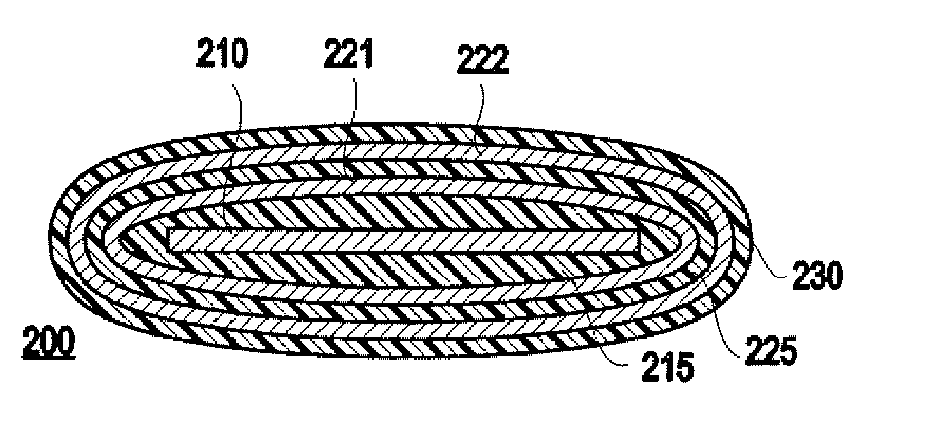
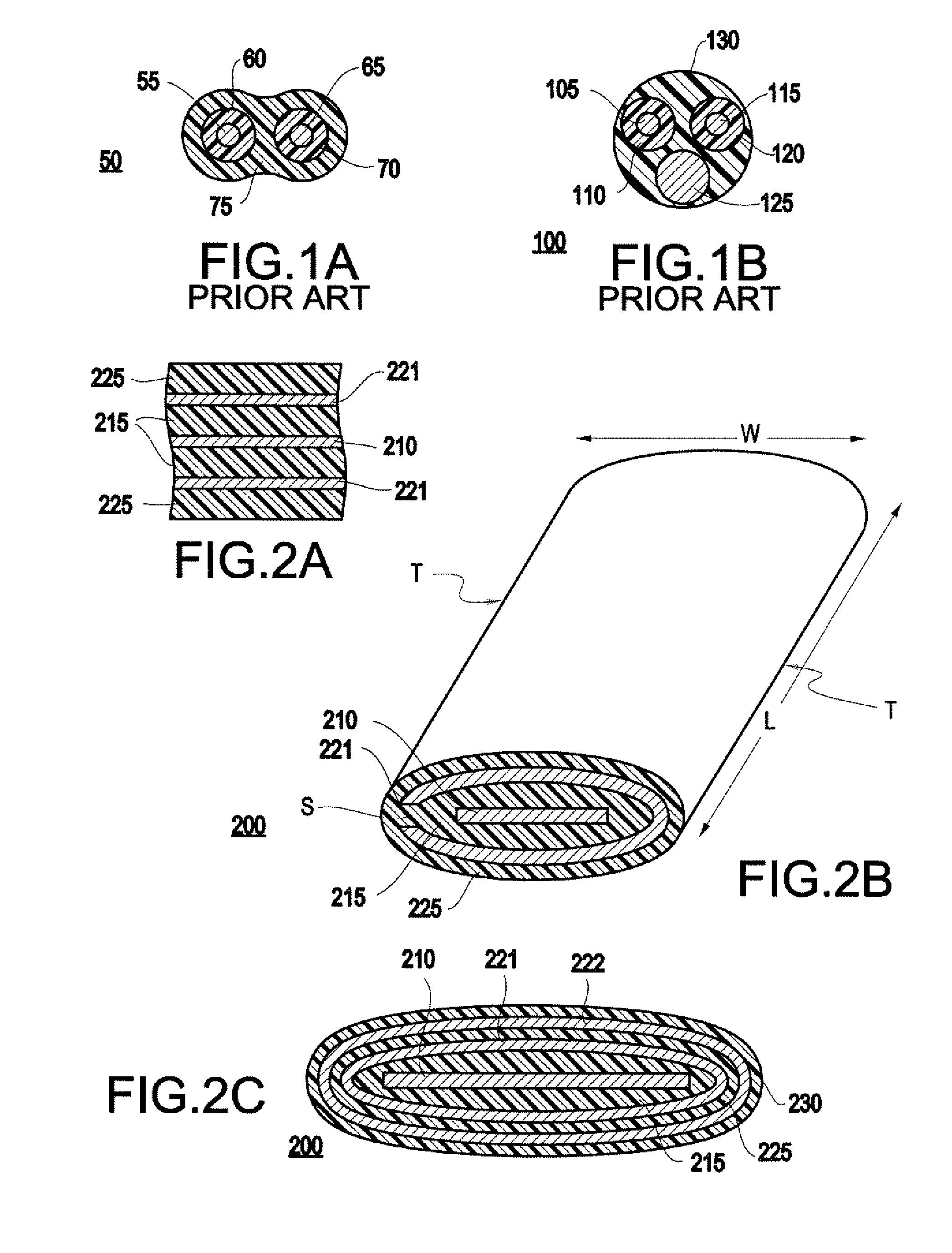
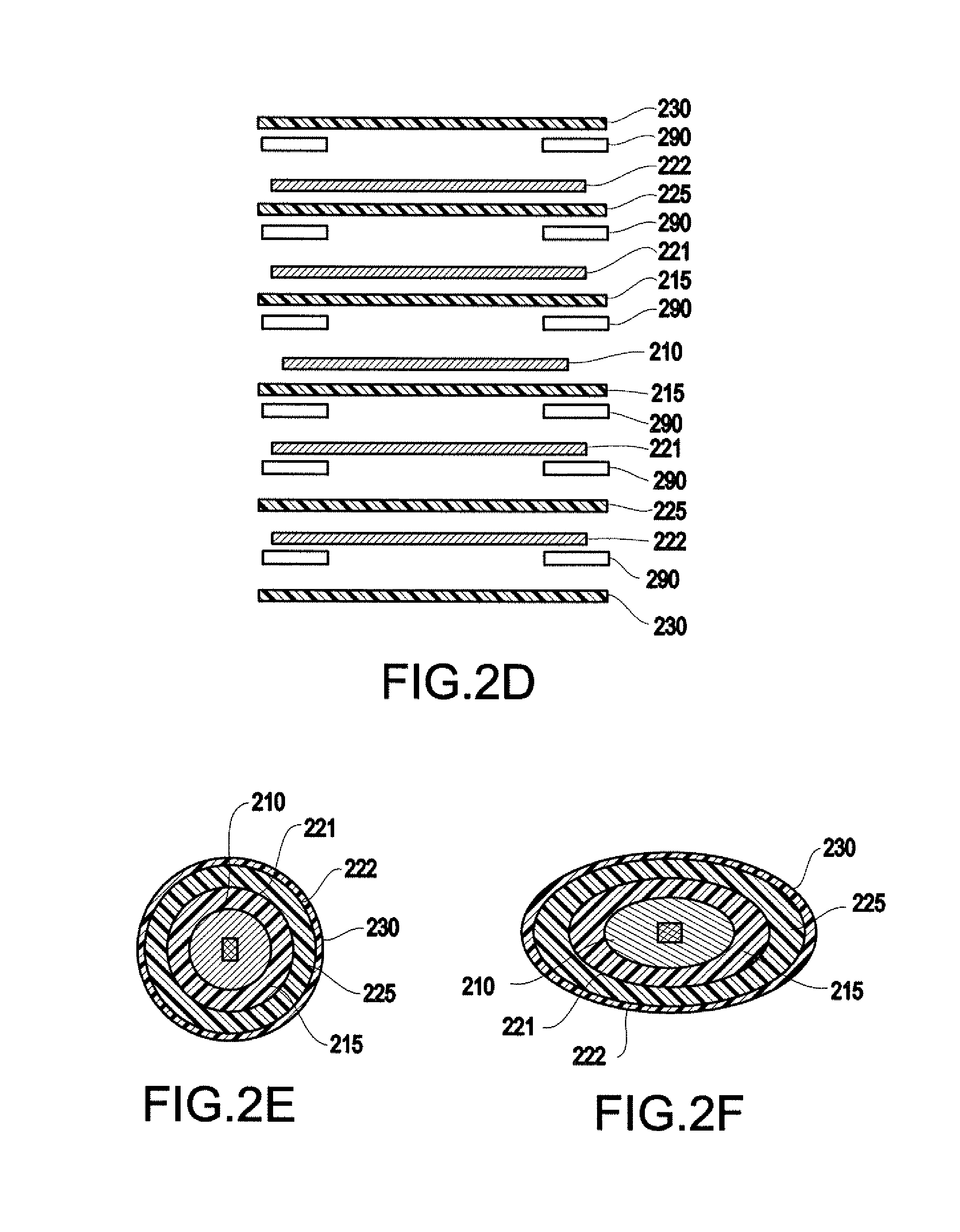
[0050] Referring now to the drawings, and more particularly to FIGS. 2A-17, the present invention includes an electrical wire 200 and a method 1500 of fabricating the electrical wire. As illustrated in FIG. 2A, an the exemplary embodiment of present invention is directed to an electrical wire 200 including at least one electrifiable conductor 210, and first and second return conductors 221 which are respectively formed on opposing sides of the at least one electrifiable conductor 210, such that the at least one electrifiable conductor is at least substantially entrapped by the first and second return conductors 221. The wire 200 may also include a first insulating layers 215 and second insulating layers 225.

[0051] It should be noted that unless otherwise noted, any of the layers (e.g., conductors, insulating layers, etc.) in the present invention and discussed herein may be formed of a plurality of layers. Thus, for example, insulating layer 215 should be construed as at least one ...


PUM

PropertyMeasurementUnit
distanceaaaaaaaaaa
thicknessaaaaaaaaaa
distanceaaaaaaaaaa

Abstract

An electrical wire includes at least one electrifiable conductor for delivering electrical power, a first insulating layer formed on one side of the electrifiable conductor, a second insulating layer formed on the opposite side of the electrifiable conductors, a first return conductor formed on the first insulating layer opposite the at least one electrifiable conductor, and a second return conductor formed on the second insulating layer opposite the at least one electrifiable conductor. The at least one electrifiable conductor is at least substantially entrapped by the first and second return conductors such that the distance between said at least one electrifiable conductor and each of said first and second return conductors is no greater than approximately 0.030 inches. At least one of the first insulating layer or the second insulating layer comprises a plurality of insulating layers.

Description

CROSS REFERENCES TO RELATED APPLICATIONS [0001] The present application is a continuation-in-part of co-pending U.S. application Ser. No. 11 / 688,020, filed Mar. 19, 2007, entitled “Electrical Wire and Method of Fabricating the Electrical Wire,” which is a continuation of U.S. application Ser. No. 11 / 437,992, filed May 19, 2006, entitled “Electrical Wire and Method of Fabricating the Electrical Wire” (now U.S. Pat. No. 7,217,884), which is a continuation of U.S. application Ser. No. 10 / 790,055, filed Mar. 2, 2004, entitled “Electrical Wire and Method of Fabricating the Electrical Wire” (now U.S. Pat. No. 7,145,073), which claims benefit of U.S. Provisional Application No. 60 / 500,350, filed Sep. 5, 2003. The disclosures of each of these applications are incorporated by reference herein in their entirety.FIELD OF THE INVENTION [0002] The present invention generally relates to an electrical wire and method of fabricating the wire, and more particularly, an electrical wire which includes...

Claims


Application Information

Patent Timeline
Patent Type & Authority Applications(United States)
IPC IPC(8): H01B7/00
CPCH01B7/0216Y10T29/49117H01B9/04H01B9/006
Inventor SEXTON, ROBERT J.MARTIN, FRED LANEGARRIS, CHARLES ALEXANDER
Owner NEWELL CO INC
Why Eureka
Try Eureka