Fluid Discharging Device

a technology of discharge device and discharge pipe, which is applied in the direction of gaseous fuel burner, combustion process, electrical apparatus, etc., can solve the problems of not satisfying the result or even the destruction

Inactive Publication Date: 2008-02-28
LAM RES AG
View PDF6 Cites 20 Cited by
  • Summary
  • Abstract
  • Description
  • Claims
  • Application Information

AI Technical Summary

Benefits of technology

[0017] In yet another embodiment of the fluid discharging device the outer nozzle is operatively connected to a vacuum source. This is advantageous if the inner nozzle is for supplying an aerosol because an uncontrolled distribution of repelled liquid droplets can be minimized because such repelled droplets are sucked thr

Problems solved by technology

This may lead to a not satisfying result or

Method used


Image

  • Fluid Discharging Device
  • Fluid Discharging Device
  • Fluid Discharging Device

Examples


Embodiment Construction

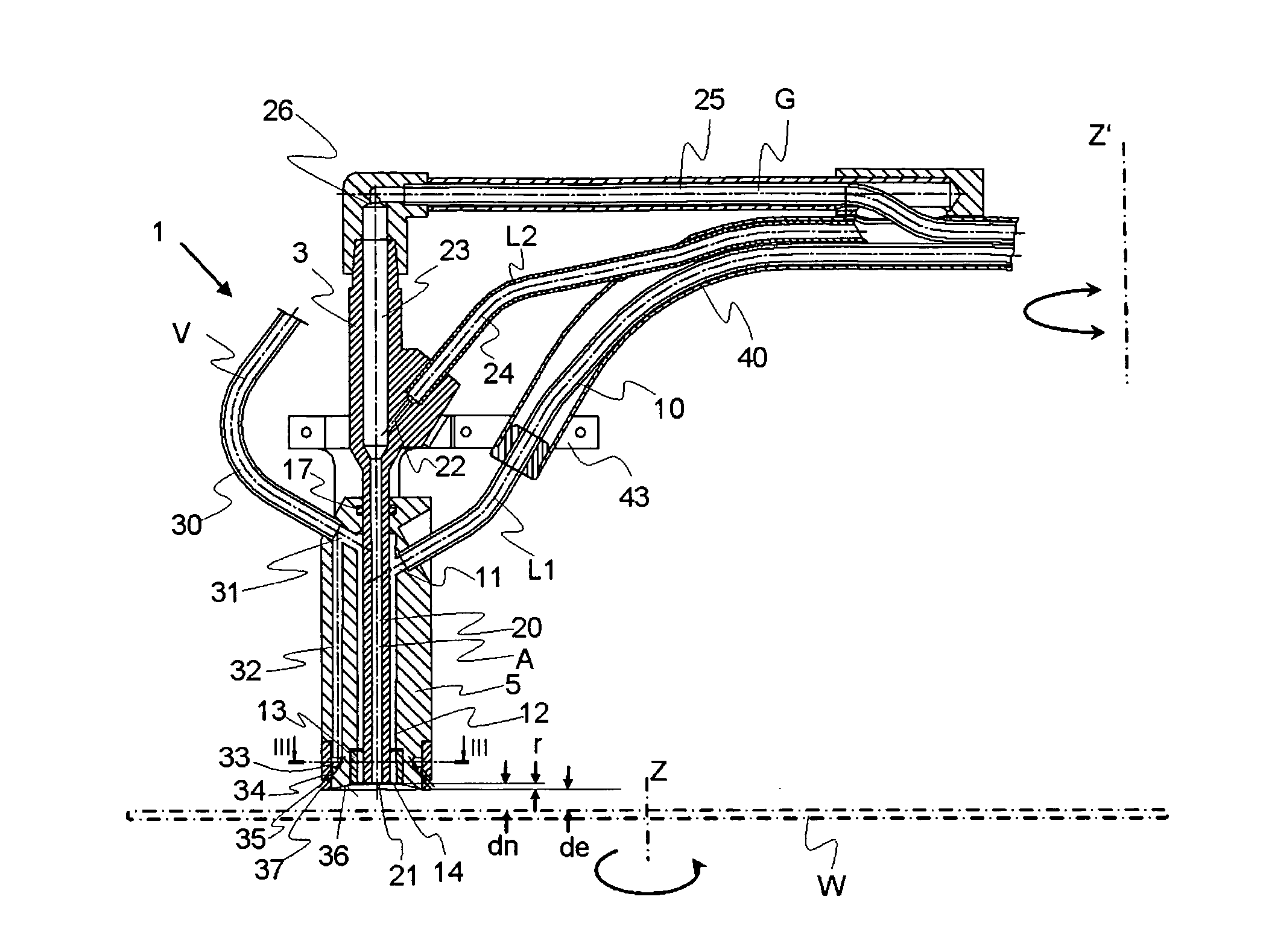
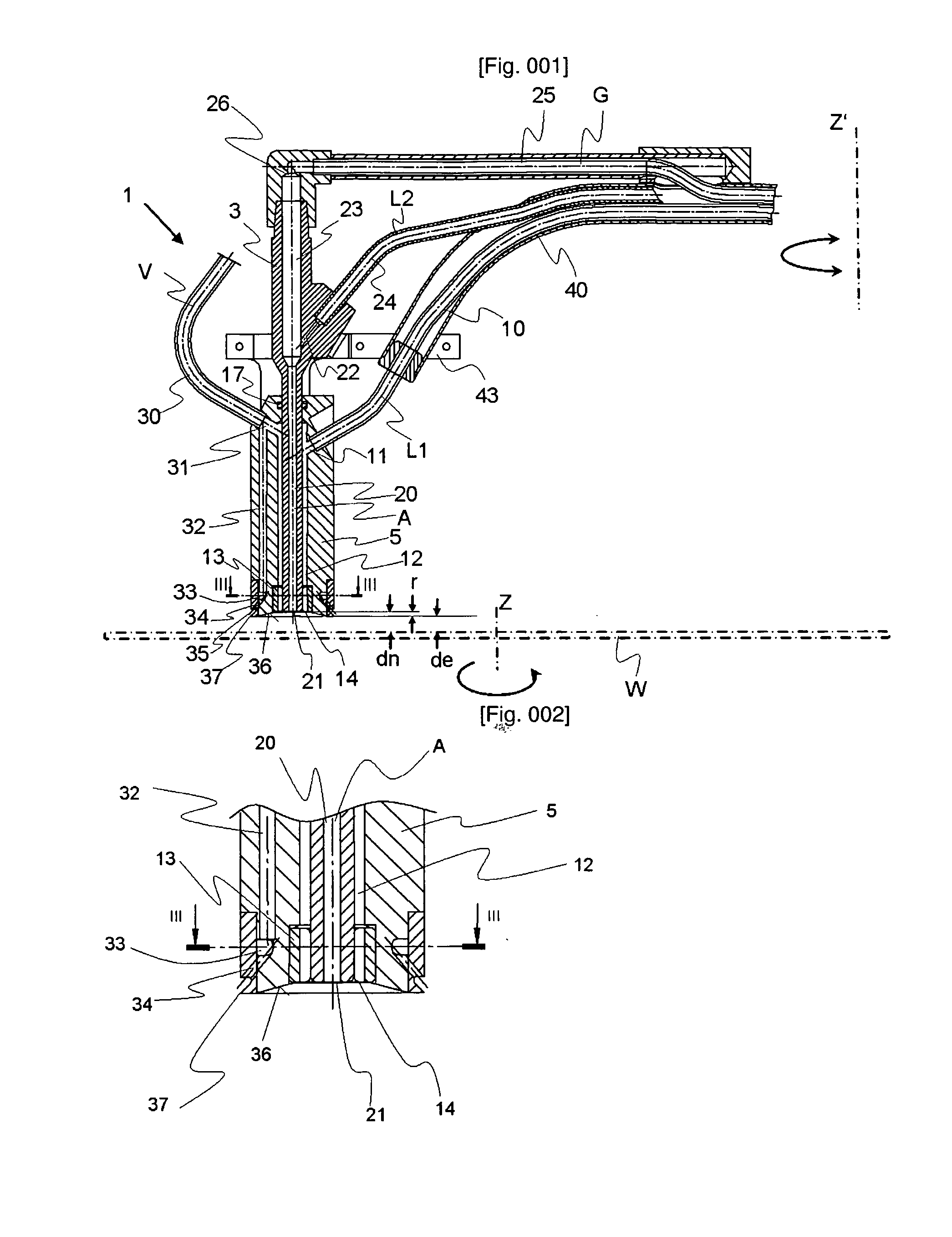
[0026] With reference to FIG. 1, FIG. 2 and FIG. 3 preferred embodiments shall be described. The fluid discharging device 1 comprises a base body 5 having a cylindrical form with an axial cylindrical opening in order to receive an inserted inner nozzle 3. The inner nozzle 3 is sealed against base body 5 with seal 15 and may be further fixed at its mouth 21 against the base body 5, e.g. with a tube like portion 13. Between the outer wall of inner nozzle 3 and the inner wall of base body 5 the outer nozzle 12 is formed.

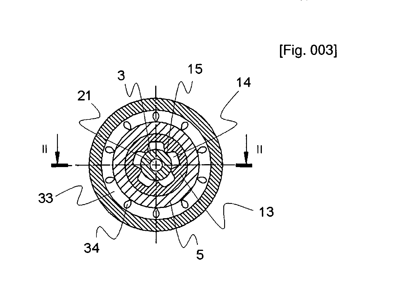
[0027] The tube like portion 13 has ribs 15 at its inner wall. The ribs 15 on the one hand fix the inner nozzle 3 and on the other hand form openings for the orifice 14 of the outer nozzle 12 so that plural streams of fluid may be discharged. FIG. 3 shows five ribs 15 which result in five opening of the nozzles orifice 14—however for securely fixing nozzle 3 at its mouth against base body 5 three ribs will be sufficient. Alternatively the inner nozzle 3 may be welded t...


PUM


Abstract

The invention relates to a fluid discharging device for separately discharging at least two fluids comprising an inner nozzle for discharging a first fluid and a coaxially arranged outer nozzle for discharging a second fluid. Such a fluid can be liquid or gas or a mixture thereof. Mixtures of liquid or gas comprise fluids having gas as the continuous phase and liquid as the disperse phase (e.g. aerosols) and fluids having liquid as the continuous phase and gas as the disperse phase (e.g. carbonated water). The invention further relates to a device and a method for wet treating a flat disc-like substrate, such as semiconductor wafers, flat panel displays or compact discs utilizing such a fluid discharging device. If in the following the term wafer is used, such disk-like substrates are meant.

Description

TECHNICAL FIELD [0001] The invention relates to a fluid discharging device for separately discharging at least two fluids. Such a fluid can be liquid or gas or a mixture thereof. Mixtures of liquid or gas comprise fluids having gas as the continuous phase and liquid as the disperse phase (e.g. aerosols) and fluids having liquid as the continuous phase and gas as the disperse phase (e.g. carbonated water). [0002] The invention further relates to a device and a method for wet treating a flat disc-like substrate, such as semiconductor wafers, flat panel displays or compact discs utilizing such a fluid discharging device. If in the following the term wafer is used, such disk-like substrates are meant. BACKGROUND ART [0003] Such fluid discharging devices are often used in semiconductor industry e.g. for discharging different liquids (e.g. etchants, cleaning liquids) and gases (e.g. corrosive, non-corrosive, inert) onto a wafer. [0004] U.S. Pat. No. 4,903,717 discloses a liquid dischargin...

Claims


Application Information

Patent Timeline
IPC IPC(8): B05B7/08B05C5/00B05B7/04B05B7/06B05B15/04H01L21/00
CPCB05B7/0416B05B7/065B05B15/0406H01L21/6708H01L21/67051H01L21/67075H01L21/6704
Inventor PICHLER, STEFAN
Owner LAM RES AG
Why Eureka
Try Eureka