Uncooled Infrared Camera System for Detecting Chemical Leaks and Method for Making the Same

a technology of infrared camera and chemical leakage, which is applied in the field of infrared cameras, can solve the problems of significant energy required to maintain an infrared detector, and achieve the effect of improving the signal to noise ratio

Inactive Publication Date: 2008-02-28
PACIFIC ADVANCED TECH
View PDF13 Cites 27 Cited by
  • Summary
  • Abstract
  • Description
  • Claims
  • Application Information

AI Technical Summary

Benefits of technology

[0010]The apparatus described above results in an improved signal to noise ratio for the image produced by the uncooled infrared camera system. The traditional method used for uncooled infrared detectors is to heat them above ambient using a thermoelectric cooler. For example and as described below, when a thermoelectric cooler is used to cool the radiation shield unit, the infrared detector and the bandpass filter to below the ambient temperature, at about 289 K, the signal to noise improvement of the camera is such that a gas leak signal that is obtained is about 3 orders of magnitude smaller compared to the gas leak signal obtained using an uncooled infrared camera system operated in the normal mode of operation. The normal mode of operation for an uncooled infrared camera system is to keep it at an elevated temperature above ambient temperature. The improvement in the signal to noise ratio allows narrow band infrared imaging of chemical gases that have absorption bands matching the bandpass filter.

Problems solved by technology

A significant amount of energy is required to maintain an infrared detector at low cryogenic temperatures.

Method used


Image

  • Uncooled Infrared Camera System for Detecting Chemical Leaks and Method for Making the Same
  • Uncooled Infrared Camera System for Detecting Chemical Leaks and Method for Making the Same
  • Uncooled Infrared Camera System for Detecting Chemical Leaks and Method for Making the Same

Examples


Embodiment Construction

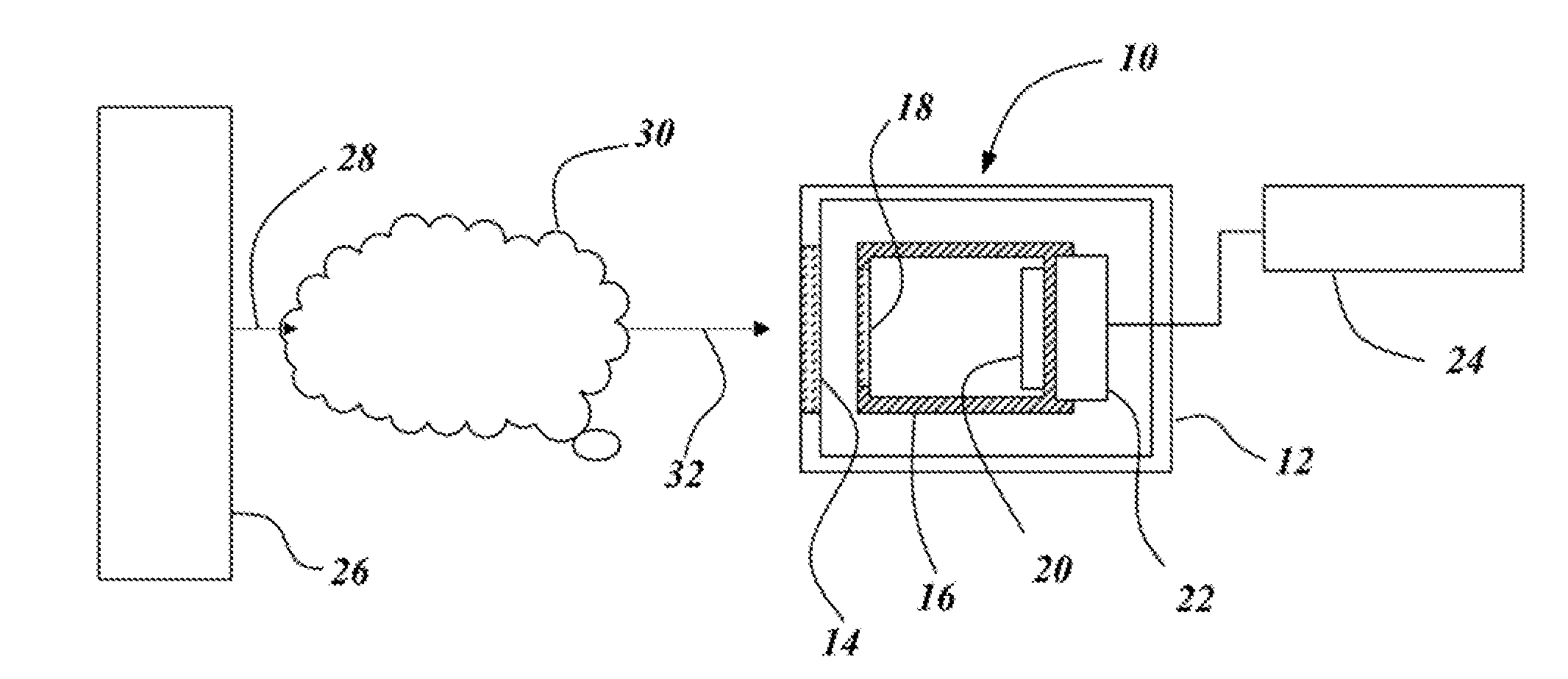
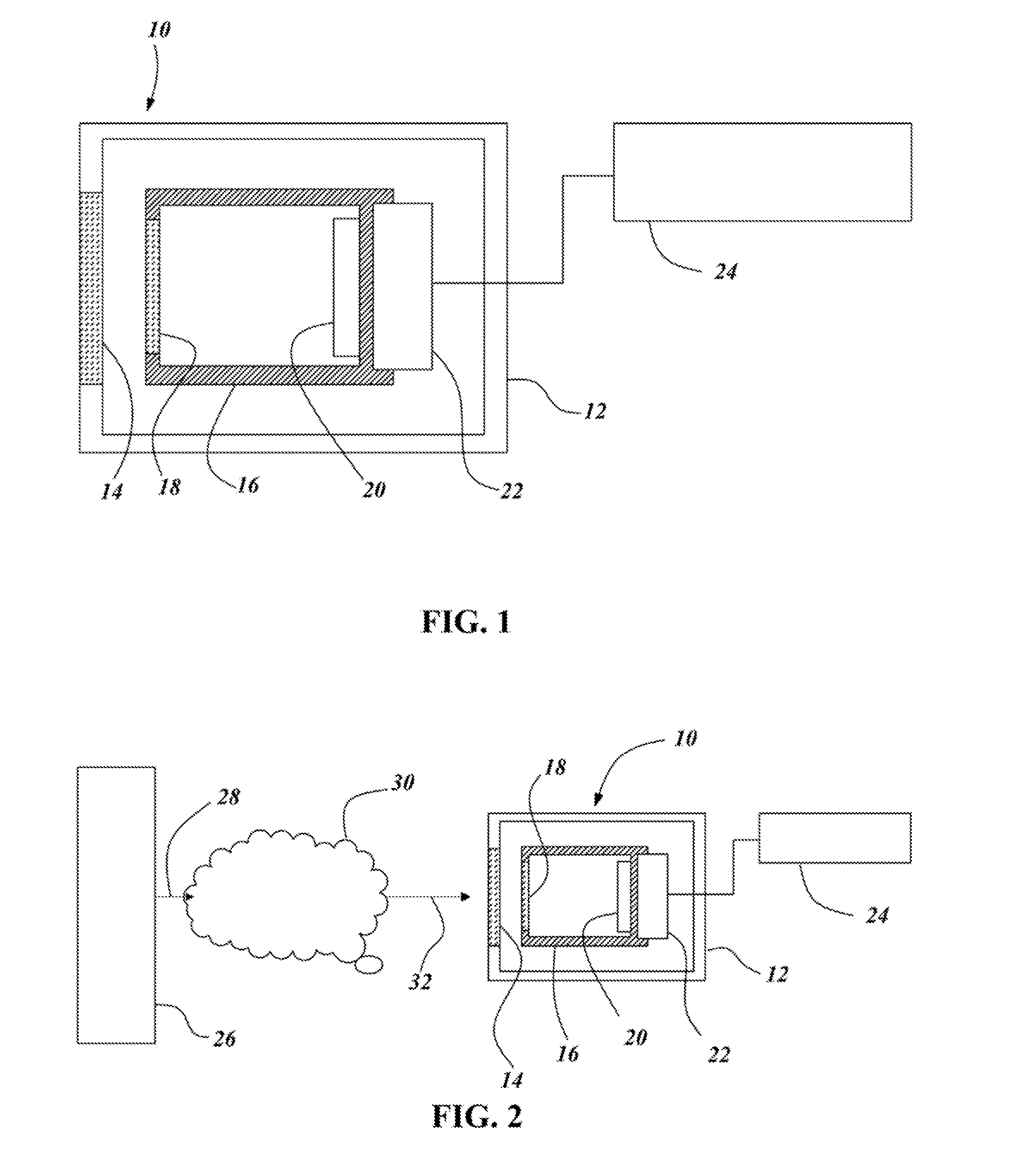
[0017]FIG. 1 is a schematic diagram of an uncooled infrared camera system 10, according to a preferred embodiment of the invention. The uncooled infrared camera system 10 is adapted to provide visible imaging of chemical fluids including gases and liquids. The chemical fluid may be a vapor or aerosol suspended in air, or a liquid on a surface. This allows the uncooled infrared camera system 10 to detect chemicals leaked or spilled in the environment.

[0018]The uncooled infrared camera system 10 includes a mechanical housing 12, at least one window or lens 14, a radiation shield unit 16, a bandpass filter 18 and an uncooled infrared detector 20, a thermoelectric cooler 22 and a temperature controller 24. The mechanical housing 12 provides structural rigidity to the uncooled infrared camera system 10 and protects the radiation shield unit 16, the band-pass filter 18, the uncooled infrared detector 20 and the thermoelectric cooler 22. The housing 12 further maintains a controlled enviro...


PUM


Abstract

An apparatus for detecting incoming radiation, including: a housing for receiving the incoming radiation, a lens attached to the housing to transmit incoming radiation into a radiation shield unit within the housing; a bandpass filter within the radiation shield unit to filter the incoming radiation falling outside a predetermined spectral band; an uncooled infrared detector within the radiation shield unit for detecting infrared radiation; wherein the bandpass filter is located along an optical path between the lens and the infrared detector; and wherein the lens optically focuses the incoming radiation onto the infrared detector. The radiation shield unit, the bandpass filter and the infrared detector are cooled to a temperature slightly less than room temperature, resulting in an improved signal to noise ratio of the image obtained.

Description

CROSS REFERENCE TO RELATED APPLICATIONS[0001]This application claims the benefit of U.S. Provisional Application No. 60 / 839,894, filed Aug. 24, 2006, which is hereby incorporated by reference in its entirety.TECHNICAL FIELD[0002]The present invention relates generally to infrared cameras. More particularly, the invention relates to an infrared camera system that is cooled to a temperature slightly less than room temperature.BACKGROUND OF THE INVENTION[0003]Infrared detectors are used to detect infrared radiation emitted by a target or generally present in the atmosphere. There are two generic types of infrared detectors, those that must be cooled to cryogenic temperatures and those that do not. The ones that operate at near ambient temperatures or are temperature controlled with a thermo-electric cooler are traditionally called uncooled infrared detectors. A significant amount of energy is required to maintain an infrared detector at low cryogenic temperatures.SUMMARY OF THE INVENTI...

Claims


Application Information

Patent Timeline
Patent Type & Authority Applications(United States)
IPC IPC(8): G01J5/10
CPCG01J5/061G01J2005/0077G01J5/10
Inventor HINNRICHS, MICHELE
Owner PACIFIC ADVANCED TECH
Why Eureka
Try Eureka