Projector apparatus

a projector and equipment technology, applied in the field of projector equipment, can solve the problems of affecting the use of the projector, affecting the performance of the projector, and affecting the quality of the projector, so as to reduce the final temperature of the exhaust air, and improve the proportion of cool air

Active Publication Date: 2008-02-28
SANYO TECH CENT SHENZHEN +1
View PDF7 Cites 15 Cited by
  • Summary
  • Abstract
  • Description
  • Claims
  • Application Information

AI Technical Summary

Benefits of technology

[0015]More particularly, the first exhaust fan is installed with its air inspiration face oriented to the light source, while the second exhaust fan is installed with its air inspiration face oriented to an area away from the light source, so that two streams of air expired from the respective exhaust fans are directed to intersect each other. Specifically, the angle between the two intersecting air streams is set in the range from 40 to 60 degrees, which ensures sufficient mixing of the air flows from the first

Problems solved by technology

However, since the exhaust unit is orientated to the hot lamp so as to inspire air heated by the lamp, the air discharged from the exhaust unit is heated to a high temperature, which makes the user of the projector unpleasant when he is exposed to the hot air.
Hence, in order to lower the temperature of the exhausted air, the exhaust fan of the exhaust unit mus

Method used


Image

  • Projector apparatus
  • Projector apparatus
  • Projector apparatus

Examples


Embodiment Construction

[0050]An LC projector apparatus embodying the invention will now be described in detail with reference to the accompanying drawings. In what follows, the “front” side of the projector apparatus refers to the side thereof having its projection lens (FIG. 1), and the “right” and “left” of the LC projector apparatus refer to the directions to the “right” and “left” relative to the front side, respectively.

General Arrangement of the Projector Apparatus

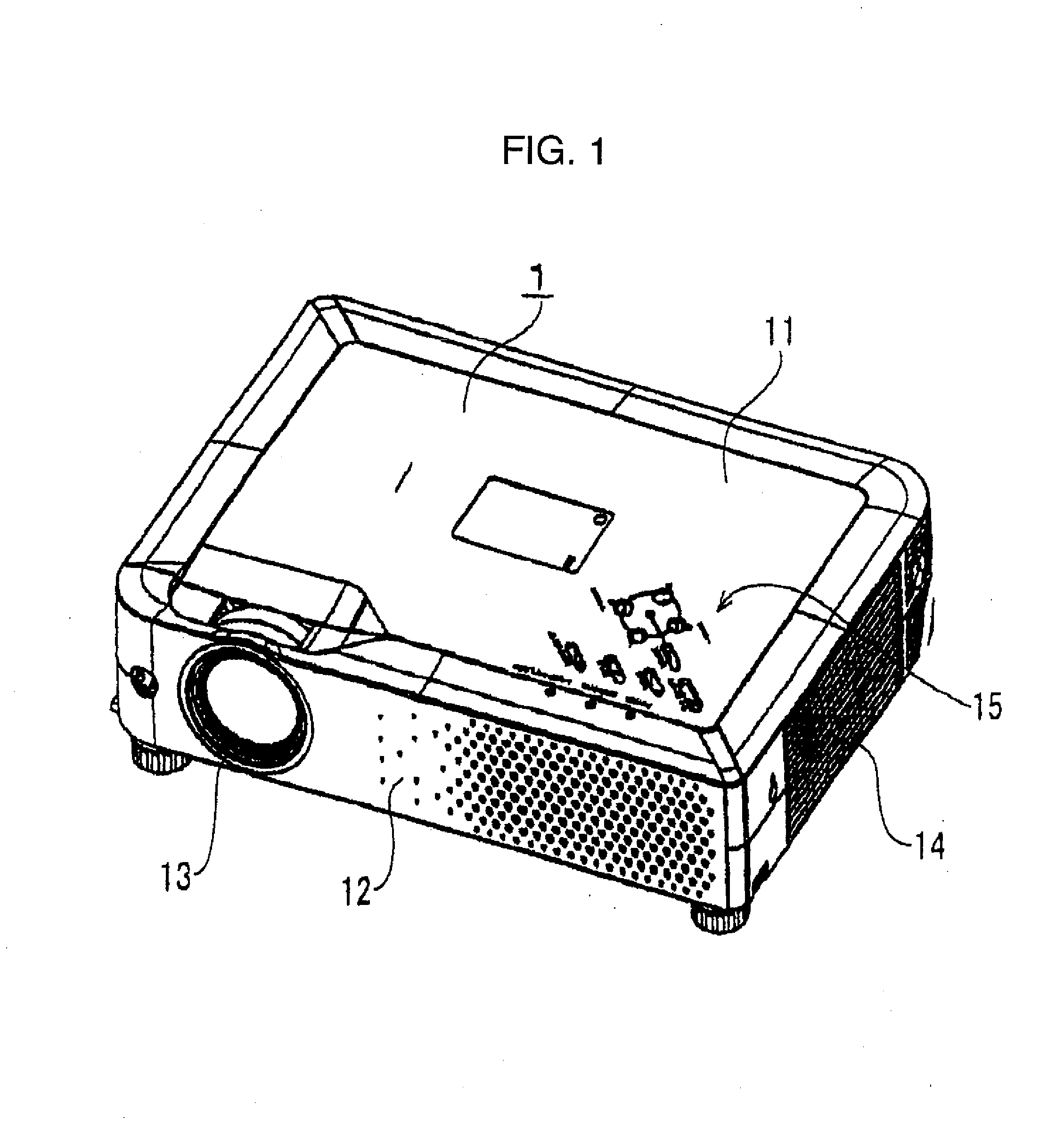
[0051]As shown in FIG. 1, an LC projector apparatus of present invention has a generally flat casing 1 which includes an upper half section 11 and a lower half section 12 of the casing 1. Provided on the upper end of the casing 1 is a controller 15 having a multiplicity of buttons for manual operation of the projector apparatus. Formed in the front end is a projection window 13. In addition, an exhaust 14 is provided in the right wall of casing 1 to exhaust the air in the casing 1 out of the casing 1.

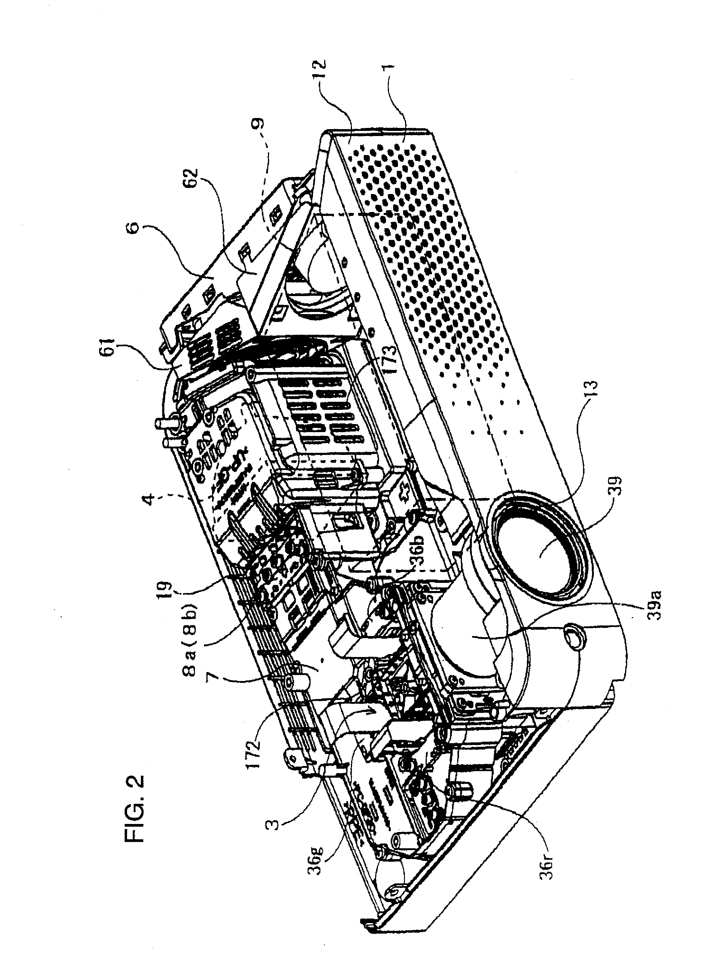
[0052]As shown in FIGS. 2 and 3, a gene...


PUM


Abstract

This invention provide a projector apparatus enabled to lower its exhaust air temperature by adding only minor modifications to the existing structure, without altering its basic structure. The liquid crystal projector apparatus of the invention has a casing (1) for accommodating therein a light source (4), an optical system adapted to construct imaging light in response to a beam of light received from the light source, a power supply (9), and a cooling unit (6) mounted on the side wall of the casing (1) to cool the components in the casing. Provided on the inner wall of the casing is an air inspiration mechanism (16, 17, 18, 126) in association with the exhaust unit (6), whereby the exhaust unit (6) can inspire ambient air through the air inspiration mechanism to lower the temperature of the air to be expired from the exhaust unit.

Description

FIELD OF THE INVENTION[0001]Present invention relates to a projector apparatus equipped with an optical system adapted to construct imaging light from light received from a light source and project an enlarged beam of imaging light onto a front screen.BACKGROUND OF THE INVENTION[0002]This type of conventional projector apparatuses are equipped with a lamp serving as a light source and an optical system having such elements as a polarization beam splitter, polarization plates, liquid crystal panels (LCPs), and a projection lens, all housed in a casing. Provided on a wall of the casing is an exhaust unit adapted to create an air flow inside the casing to suppress temperature rise in the casing. (See for example, Japanese Patent Application Laid Open No. H8-275096.)[0003]However, since the exhaust unit is orientated to the hot lamp so as to inspire air heated by the lamp, the air discharged from the exhaust unit is heated to a high temperature, which makes the user of the projector unp...

Claims


Application Information

Patent Timeline
IPC IPC(8): G03B21/16
CPCG03B21/16
Inventor ZHENG, WANJUNSARUWATARI, TOSHIHIROZHANG, XIANGLIN
Owner SANYO TECH CENT SHENZHEN
Why Eureka
Try Eureka