Segmented auger for a concrete dispensing apparatus

a concrete and segmented technology, applied in the field of segmented augers, can solve the problems of frequent maintenance, service and repair of the auger, and achieve the effects of convenient disassembly of the auger mechanism, convenient disassembly and assembly, and low manufacturing cos

Inactive Publication Date: 2008-02-28
SUPERIOR WALLS OF AMERICA
View PDF20 Cites 14 Cited by
  • Summary
  • Abstract
  • Description
  • Claims
  • Application Information

AI Technical Summary

Benefits of technology

[0015]It is yet another advantage of this invention that the disconnection of the auger shaft from the jack shaft carried by the interior bearing permits a disassembly of the auger mechanism.
[0016]It is a further advantage of this invention that the auger mechanism can be disassembly to permit a quick removal and replacement of the auger mechanism in the concrete dispensing apparatus.
[0017]It is still another object of this invention to provide an auger mechanism for use in a concrete dispensing apparatus for use in the manufacture of pre-cast concrete wall panels, which is durable in construction, inexpensive of manufacture, carefree of maintenance, facile in assemblage, and simple and effective in use.
[0018]These and other objects, features and advantages are accomplished according to the instant invention by providing a segmented auger mechanism in the hopper of a concrete dispensing ap...

Problems solved by technology

Operating an auger in a harsh environment, such as for the distribution and conveying of a hydrated concrete mixture, requires frequent maintenance, service and repair of the auger.
The time required to...

Method used


Image

  • Segmented auger for a concrete dispensing apparatus
  • Segmented auger for a concrete dispensing apparatus
  • Segmented auger for a concrete dispensing apparatus

Examples


Embodiment Construction

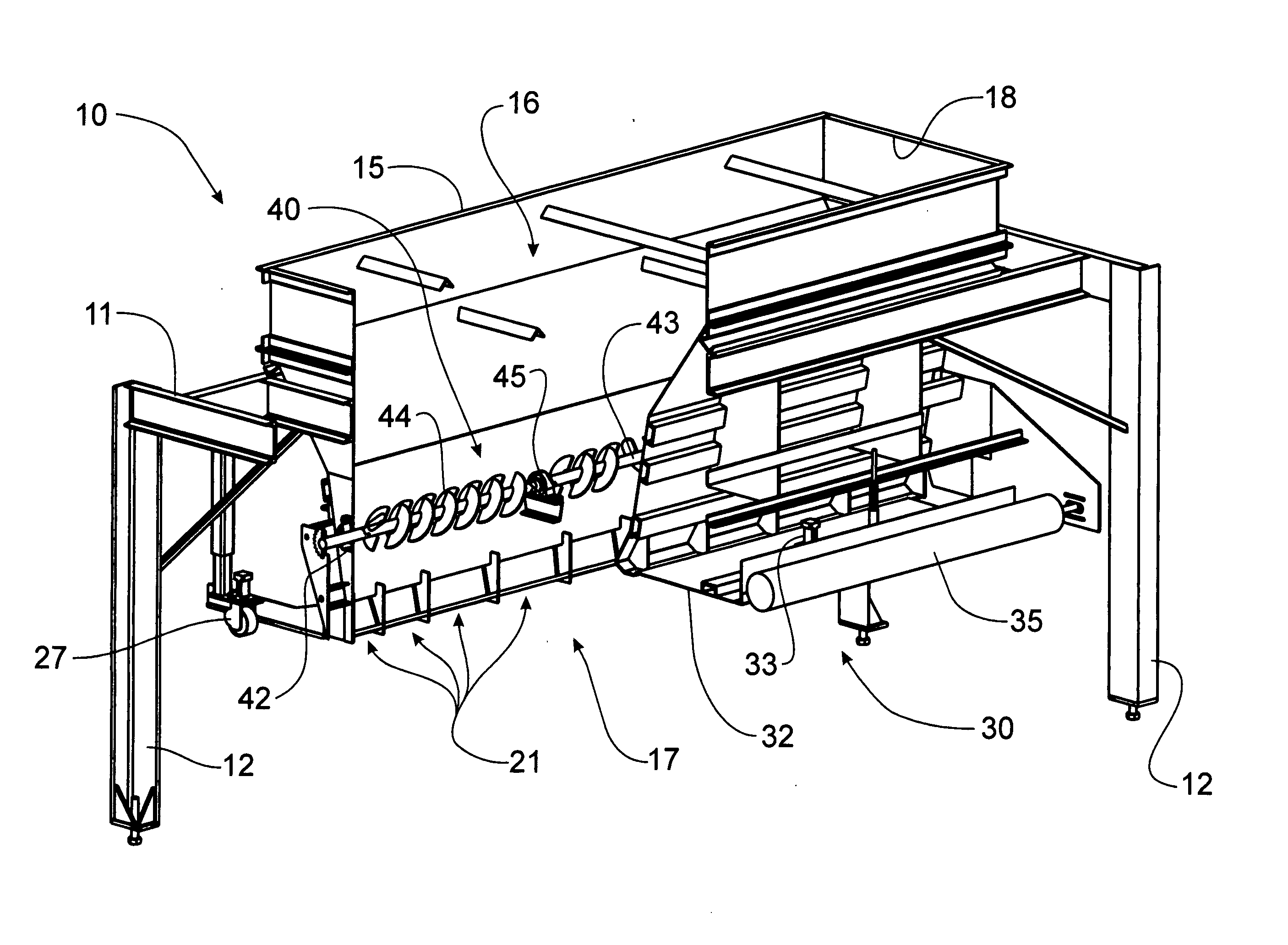
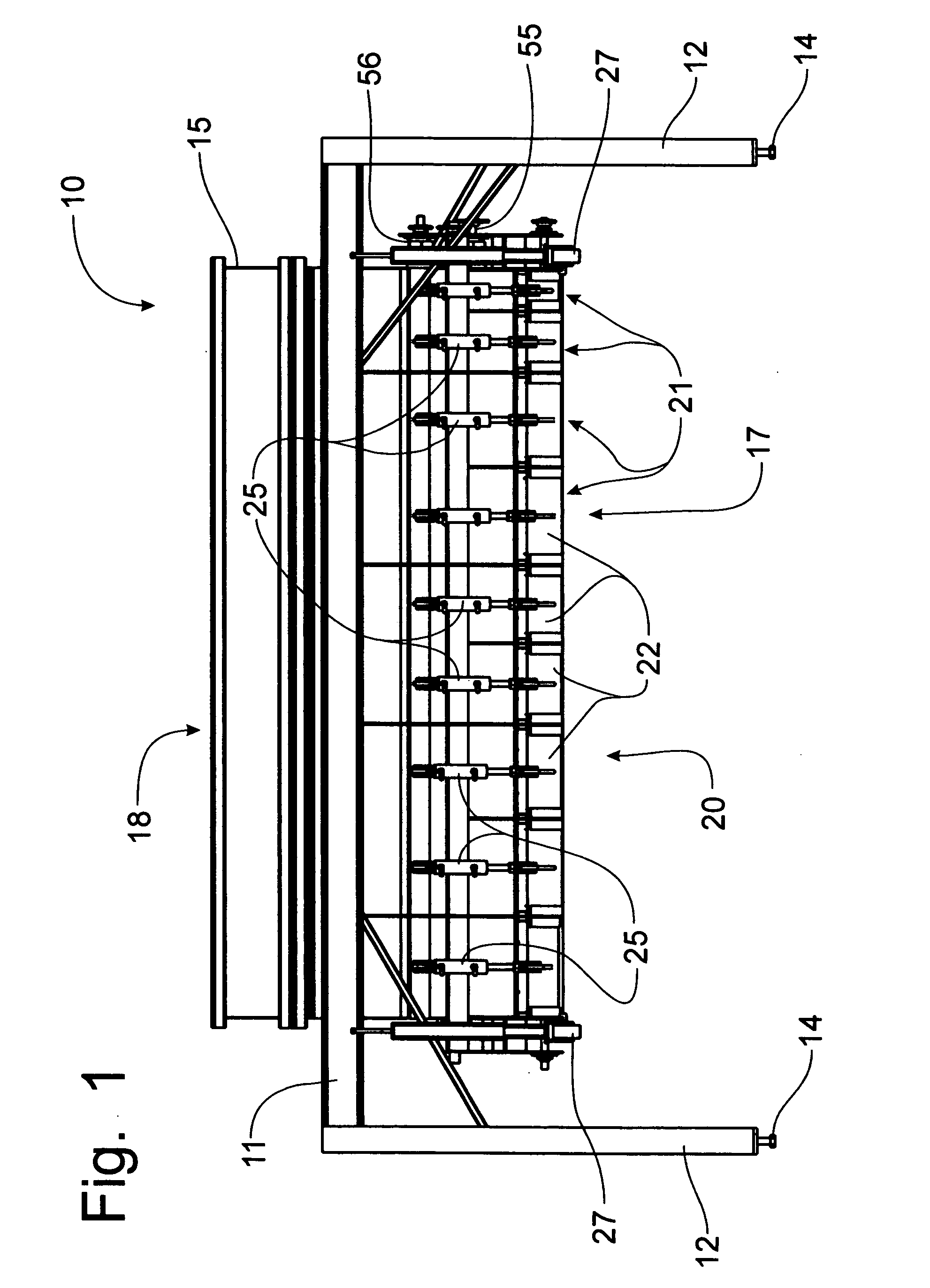
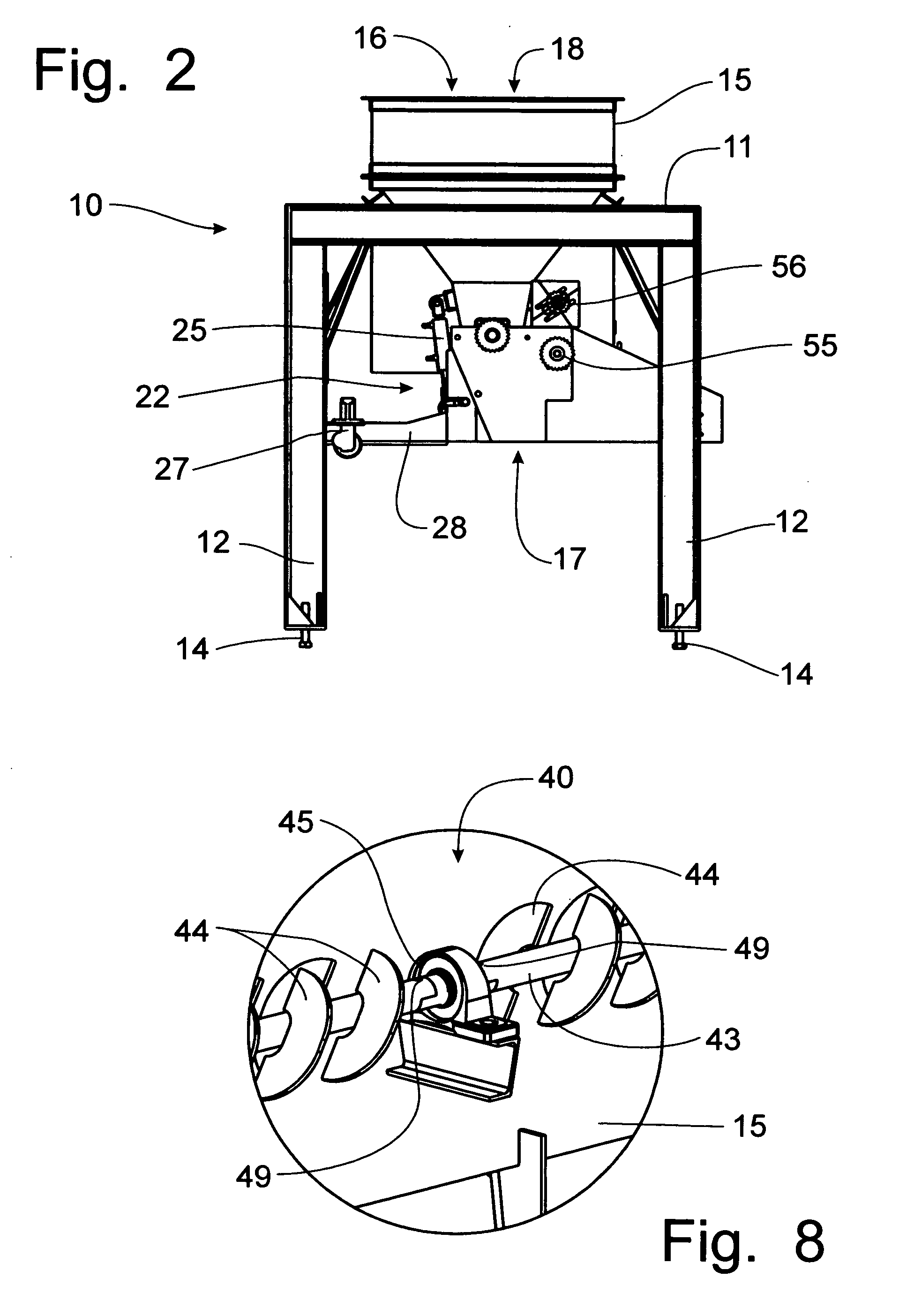
[0033]Referring now to FIGS. 1-6, an apparatus for dispensing a concrete mixture into a form can best be seen. The apparatus is intended for use in conjunction with forms for making pre-cast concrete structures, such as foundation wall sections that can be transported to a building site and assembled to create a foundation for the residential or commercial building to be constructed. In the forms that are assembled for creating such modular concrete foundation wall panels, openings for doors or windows are required. While the concrete mixture is to be poured generally into the wall panel form, the concrete mixture is not to be poured into the openings that are also configured into the form. The concrete dispenser 10 to be described below is intended to be moved relative to the modular foundation wall panel form to be filled with concrete mixture. The concrete dispenser 10 can be moved relative to the form, or the form can be moved relative to a fixed position concrete dispenser 10. ...


PUM


Abstract

A segmented auger mechanism is mounted in the hopper of a concrete dispensing apparatus used to distribute a hydrated concrete mixture into a horizontally disposed form to manufacture pre-cast concrete structures, such as concrete wall panels used to form a foundation for a residential or commercial building. The auger mechanism is formed of connected segments that can be individually and independently removed from the concrete structure for service and repair. The auger is rotatably supported by a pair of end bearings supported on the opposing end walls of the hopper of the dispensing apparatus, and by at least one interior bearing rotatably supporting a jack shaft having opposing half-round connecting portions for attachment to a corresponding connecting portion on the auger shaft. Removal of a segment of the auger mechanism facilitates the removal of the entire auger mechanism to minimize the down time of the concrete dispensing apparatus.

Description

FIELD OF THE INVENTION[0001]The present invention relates generally to the formation of pre-cast concrete structures, and, more particularly, to an auger disposed in a dispensing apparatus for distributing concrete mixture into a form corresponding to the pre-cast concrete structure.BACKGROUND OF THE INVENTION[0002]Pre-cast concrete structures, such as the type disclosed in U.S. Pat. No. 4,751,803, issued to Melvin M. Zimmerman on Jun. 21, 1988, are commonly utilized in the construction of foundation walls for residential and commercial buildings. Improvements to the basic pre-cast process have been made over the years, as are represented in U.S. Pat. No. 5,055,252, issued to Melvin M. Zimmerman on Oct. 8, 1991; in U.S. Pat. No. 5,656,194, granted on Aug. 12, 1997, to Melvin M. Zimmerman; and in U.S. Pat. No. 6,494,004, issued on Dec. 17, 2002, to Melvin M. Zimmerman. In generally terms, the process involves setting up the form with a polystyrene foam bottom and reinforcing members ...

Claims


Application Information

Patent Timeline
IPC IPC(8): B01F7/08B28C7/16
CPCB01F7/00425B01F7/00691B01F7/088B65G33/32B28B5/02B28B13/0215B28B13/0225B28B1/29B01F27/1144B01F27/2121B01F27/726
Inventor ZIMMERMAN, MELVIN M.MARTIN, CARL S.HILDEBRAND, MATTHEW S.
Owner SUPERIOR WALLS OF AMERICA
Why Eureka
Try Eureka