Expanded beam connector

a beam connector and beam technology, applied in the field of optical connectors, can solve the problems of higher return losses in multimode connectors and inflexibility, and achieve the effect of facilitating air gaps

Inactive Publication Date: 2008-02-28
TE CONNECTIVITY CORP
View PDF15 Cites 41 Cited by
  • Summary
  • Abstract
  • Description
  • Claims
  • Application Information

AI Technical Summary

Benefits of technology

[0013] The present invention provides an expanded beam connector configuration having an optical interface between the fiber and the lens that facilitates an air gap. Specifically, the optical interface of present invention uses a simple glass element affixed to a fiber-containing ferrule and coated with an antireflective (AR) material. Using the AR coated glass element affixed to the ferrule assembly provides for a number of important benefits.

Problems solved by technology

Such flexibility has not been available to date.
Furthermore, since an AR coated glass element may be used at the air interface for all expanded beam connectors, higher return losses are realized in the multimode connector as well.

Method used


Image

  • Expanded beam connector
  • Expanded beam connector
  • Expanded beam connector

Examples


Embodiment Construction

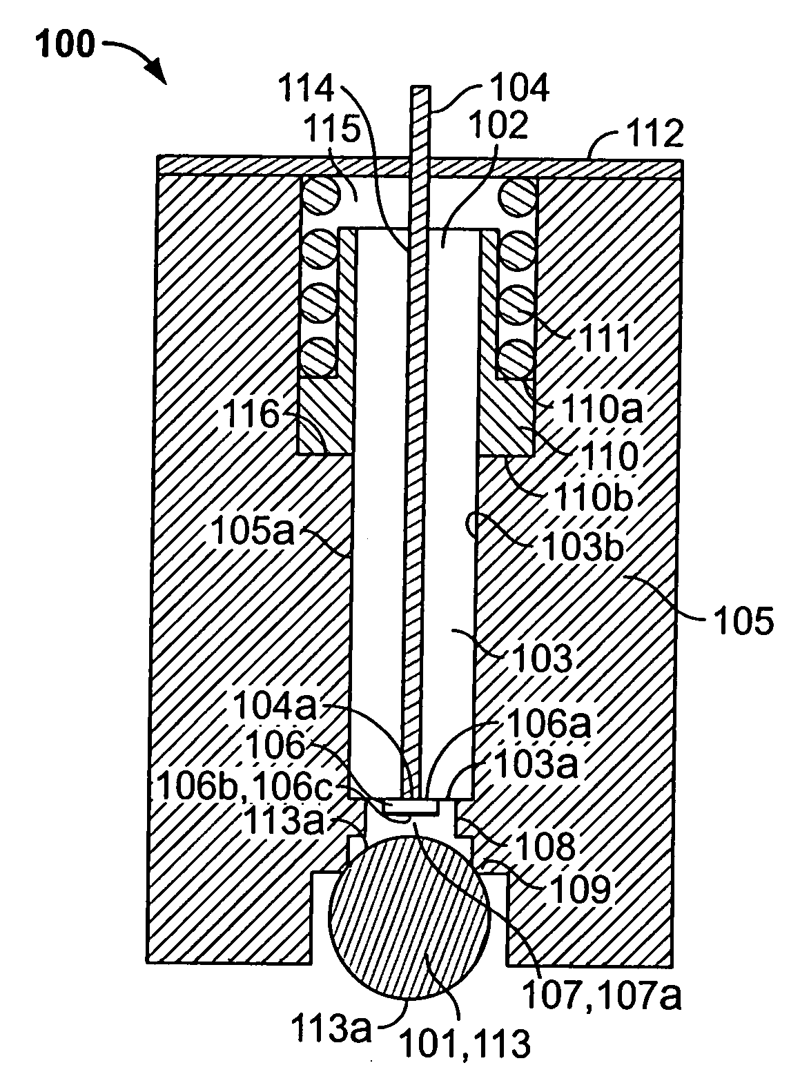
[0031] Referring to FIG. 1, an optical connector 100 of the present invention is shown. As used herein the term “connector” refers to any device used to join a segment of the conductor to (1) another conductor segment, (2) an active device such as a photonic radiation source, detector, or repeater, and (3) a passive device, such as switch, multiplexer, or attenuator. A typical optical fiber connector comprises a housing and a ferrule assembly within the housing. The ferrule assembly comprises a ferrule, which has one or more bore holes to accommodate fibers, and a fiber secured in each bore hole such that the end of the fiber is presented for optical coupling by the ferrule. The housing is designed to engage a “mating structure” having an optical path to which the fiber optically couples during mating. The mating structure may be another connector or an active or passive device as mentioned above. The optical path may be, for example, a fiber in a ferrule, a waveguide in a substrate...


PUM

PropertyMeasurementUnit
diameteraaaaaaaaaa
reflectivityaaaaaaaaaa
wavelengthsaaaaaaaaaa

Abstract

An optical connector comprising: (a) a lens; (b) a ferrule assembly comprising a ferrule with an endface and at least one fiber in the ferrule having a fiber end presented at the endface; (c) a housing for holding the ferrule assembly and the lens in a certain axial and radial relationship; and (d) a glass element having a first and second surface, the first surface affixed to the endface such that it is in physical contact with the fiber end, the second surface having an AR coating and defining a space between it and the lens.

Description

CROSS-REFERENCE TO RELATED APPLICATIONS [0001] This application claims the benefit of U.S. Provisional Application No. 60 / 834,758 filed Jul. 31, 2006.FIELD OF THE INVENTION [0002] The present invention relates generally to an optical connector, and, more specifically, to an expanded beam optical connector. BACKGROUND OF THE INVENTION [0003] Optical fiber connectors are a critical part of essentially all optical fiber communication systems. For instance, such connectors are used to join segments of fiber into longer lengths, to connect fiber to active devices, such as radiation sources, detectors and repeaters, and to connect fiber to passive devices, such as switches, multiplexers, and attenuators. The principal function of an optical fiber connector is to hold the fiber end such that the fiber's core is axially aligned with an optical pathway of the mating structure. This way, light from the fiber is optically coupled to the optical pathway. [0004] Of particular interest herein are...

Claims


Application Information

Patent Timeline
Patent Type & Authority Applications(United States)
IPC IPC(8): G02B6/36
CPCG02B6/32G02B6/4204Y10T29/49826G02B6/4292G02B6/4207
Inventor KADAR-KALLEN, MICHAEL AARONGRINDERSLEV, SORENPAUL, RANDALL BOBBY
Owner TE CONNECTIVITY CORP
Why Eureka
Try Eureka