Filament lamp and light-irradiation-type heat treatment device

a technology of heat treatment device and filament lamp, which is applied in the direction of lighting and heating apparatus, stoves or ranges, furniture, etc., can solve the problems of difficulty in giving the desired physical properties of the article being treated, quality decline, and crystal transition defects, so as to prevent unwanted discharge and maintain initial performance reliably, the effect of ensuring the stability of the filamen

Inactive Publication Date: 2008-02-28
USHIO DENKI KK
View PDF16 Cites 27 Cited by
  • Summary
  • Abstract
  • Description
  • Claims
  • Application Information

AI Technical Summary

Benefits of technology

[0017]This invention is directed to solving of the above-indicated problems. In particular, it is a primary object of the present invention to provide a filament lamp that reliably enables the desired irradiation distribution and also reliably prevents unwanted discharge between filaments or leads of neighboring filament assemblies, thus reliably preventing damage to filaments and leads even when large amounts of power are supplied to the filaments.

Problems solved by technology

When using a light-irradiation-type heat treatment device of this type to perform RTP of semiconductor wafers, for example, unevenness of the temperature distribution of a semiconductor wafer when it is heated to a temperature of 1050° C. or higher is liable to cause a phenomenon called “slip” in the semiconductor wafer, in which crystal transition defects arise and quality declines, and so it becomes necessary to heat the semiconductor wafer, hold it at a high temperature, and then cool it so that the temperature distribution will be even across the entire surface.
However, there may be small, special regions in the article to be treated that are very small relative to the length of the emitted light of the incandescent lamp, and when light irradiation is performed at a light intensity appropriate to the characteristics of these special regions, the regions other than the special regions are irradiated under the same conditions, and so it has not been possible with earlier heat treatment device to adjust temperatures to provide suitable temperature conditions for both the special regions and the other regions, or in other words, to control only the degree of irradiation of the small, special regions so that the temperature status of the article to be treated will be even.
Even in the event that light irradiation is performed so that there is the same degree of irradiation of such special regions and the other regions, there will be differences between them in the speed of temperature rise and the temperature in the special regions will not necessarily be the same as the temperature in other regions, and there may be the problem that the unwanted temperature distribution in the treatment temperature of the article being treated results in difficulty in giving the desired physical properties to the article being treated.
However, it was judged that, if the power supplied to the filament is simply increased, there is liable to be unwanted discharge between the leads of neighboring filament assemblies.
If such unwanted discharge continues over a long period, there will be the defect of the filament or the lead melting through.

Method used


Image

  • Filament lamp and light-irradiation-type heat treatment device
  • Filament lamp and light-irradiation-type heat treatment device
  • Filament lamp and light-irradiation-type heat treatment device

Examples


Embodiment Construction

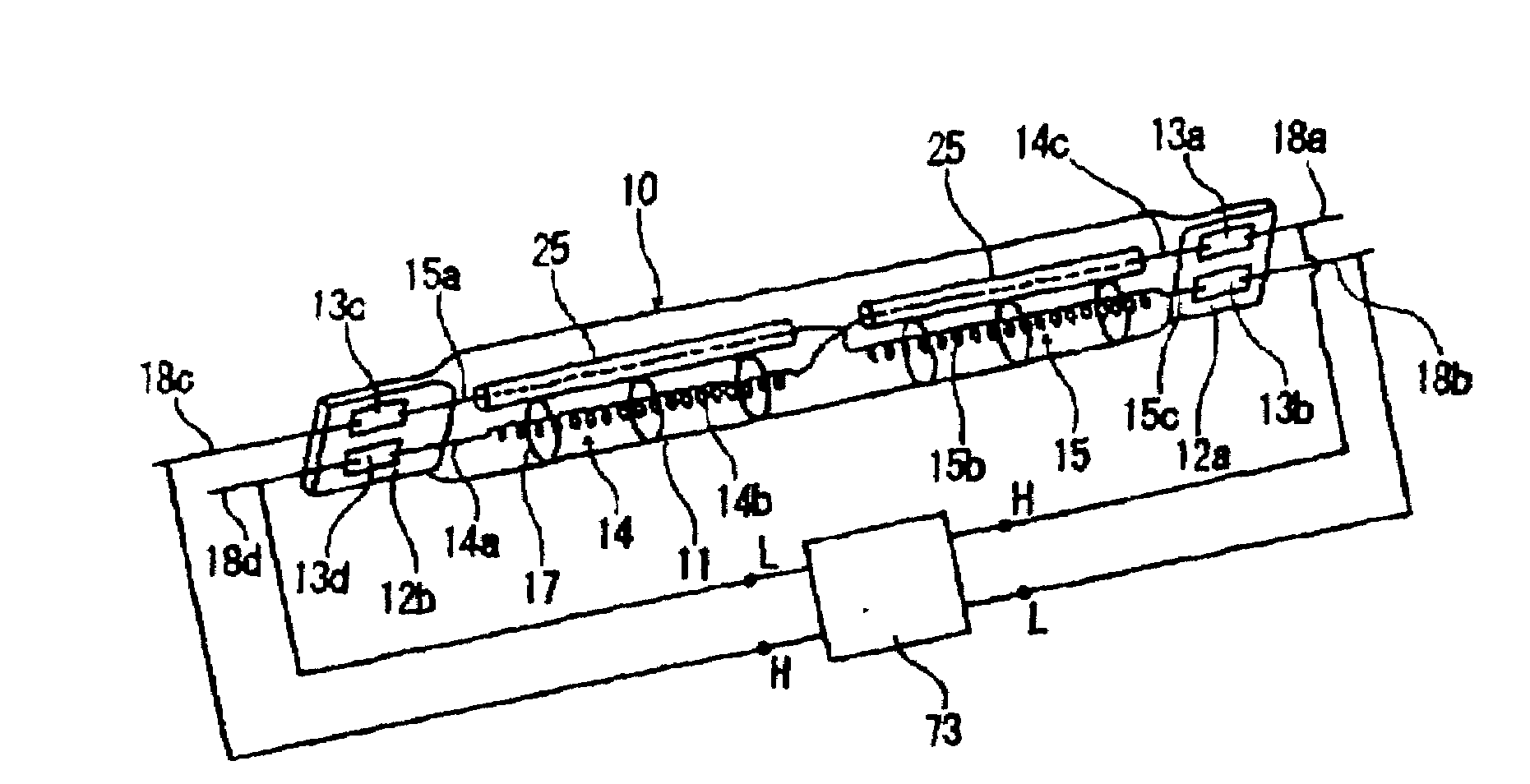
[0048]FIG. 1 is an oblique explanatory view showing an outline of the constitution of one example of the filament lamp of this invention.

[0049]With reference to FIG. 1, the filament lamp has a straight-line light emitting bulb 11 sealed at both ends, and within the light emitting bulb 11 are multiple (two are shown in FIG. 1) filament assemblies 14, 15, comprising filament coils and leads that supply electricity to the filament coils, that are orderly arranged so that the filament coils 14b, 15b extend in the axial direction of the light emitting bulb 11.

[0050]In the first filament assembly 14, a lead 14c is connected to one end of the filament coil 14b and is electrically connected to an external lead 18a that projects through a sealed portion 12a of the light emitting bulb 11, by way of a metal foil 13a sealed within the sealed portion 12a, and another lead 14a is connected to the other end of the filament coil 14b and is electrically connected to an external lead 18d that project...


PUM


Abstract

A filament lamp that allows independent control of the state of luminescence of multiple filaments and that reliably prevents the occurrence of unwanted discharge between adjacent portions of neighboring filaments, even when a high voltage is injected into the filaments to achieve a desired irradiation distribution, and light-irradiation-type heat treatment device that can heat the article to be treated uniformly. The filament lamp has multiple filament assemblies, each having a filament and respective leads arrangement sequentially within a light emitting bulb, in the axial direction of the light emitting bulb. With alternating current power supplied to each filament independently, the current will be supplied with the same phase and mutually adjacent terminals of neighboring filament assemblies will have the same potential, and with direct current power supplied to each filament independently, adjacent terminals of neighboring filament assemblies will be of the same polarity. The light-irradiation-type heat treatment device uses multiple filament lamps of this type.

Description

BACKGROUND OF THE INVENTION[0001]1. Field of the Invention[0002]This invention relates to a filament lamp and light-irradiation-type heat treatment device, and particularly, to a filament lamp used for heat treatment of an article and a light-irradiation-type heat treatment device equipped with such a filament lamp.[0003]2. Description of Related Art[0004]Heat treatment is used in a variety of processes in the manufacture of semiconductors, including film growth, oxidation, implantation of impurities, nitriding, film stabilization, silicidation, crystallization, and ion injection activation. In particular, rapid thermal processing (hereafter RTP) of a semiconductor wafer or other article to be treated by quickly raising and lowering its temperature enables improved throughput and quality, and so its use is desirable.Light-irradiation-type heat treatment devices that can heat the article to be treated without contacting it, by means of light irradiation from a light source, such as a...

Claims


Application Information

Patent Timeline
Patent Type & Authority Applications(United States)
IPC IPC(8): H01L21/26H05B1/00
CPCH01K1/16H01K1/24H05B3/0047H01K9/08H01K7/00H01K5/02
Inventor MIZUKAWA, YOICHIKITAGAWA, TETSUYASUZUKI, SHINJI
Owner USHIO DENKI KK
Why Eureka
Try Eureka