
Systems, methods and apparatus for protein folding simulation

a protein folding simulation and system technology, applied in the field of systems, methods and apparatus for protein folding simulation, can solve the problems of inability to reliably apply techniques, time-consuming and expensive techniques, and the inability to solve the underlying physical equation, known as the schrodinger equation, to achieve the effect of improving legibility

Inactive Publication Date: 2008-02-28
D WAVE SYSTEMS INC
View PDF6 Cites 32 Cited by
  • Summary
  • Abstract
  • Description
  • Claims
  • Application Information

AI Technical Summary

Benefits of technology

[0035] In the figures, identical reference numbers identify similar elements or acts. The sizes and relative positions of elements in the figures are not necessarily drawn to scale. For example, the shapes of various elements and angles are not drawn to scale, and some of these elements are arbitrarily enlarged and positioned to improve legibility. Further, the particular shapes of the elements as drawn are not intended...

Problems solved by technology

The native structure of a protein can sometimes be experimentally determined using techniques such as X-ray crystallography and NMR spectroscopy; however, these techniques are time-consuming and relatively expensive and there are classes of proteins for which both techniques cannot be reliably applied.
For molecules of this size, direct simulation of system dynamics by solving the underlying physical equation, known as the Schrodinger equation, is known to be impossible for any conventional digital computer.
Even though lattice protein models require fewer computational resources than direct solution of the true underlying physical equations, most realistic lattice protein folding models are formally intractable.
In 1981 Richard P. Feynman proposed that quantum computers could be used to solve certain computational problems more efficiently than a UTM and therefore invalidate the Church-Turing thesis.
Circuit model quantum computers have several serious barriers to practical implementation.
The art is still hampered by an inability to increase the coherence of qubits to acceptable levels for designing and operating practical circuit model quantum computers.
This technique does not guarantee finding a global minimum.

Method used


Image

  • Systems, methods and apparatus for protein folding simulation
  • Systems, methods and apparatus for protein folding simulation
  • Systems, methods and apparatus for protein folding simulation

Examples


example 1

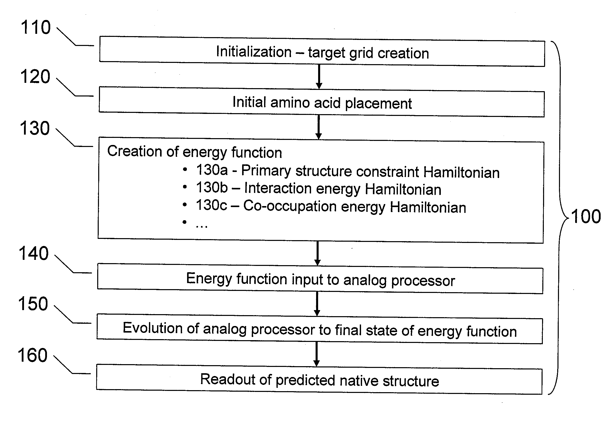
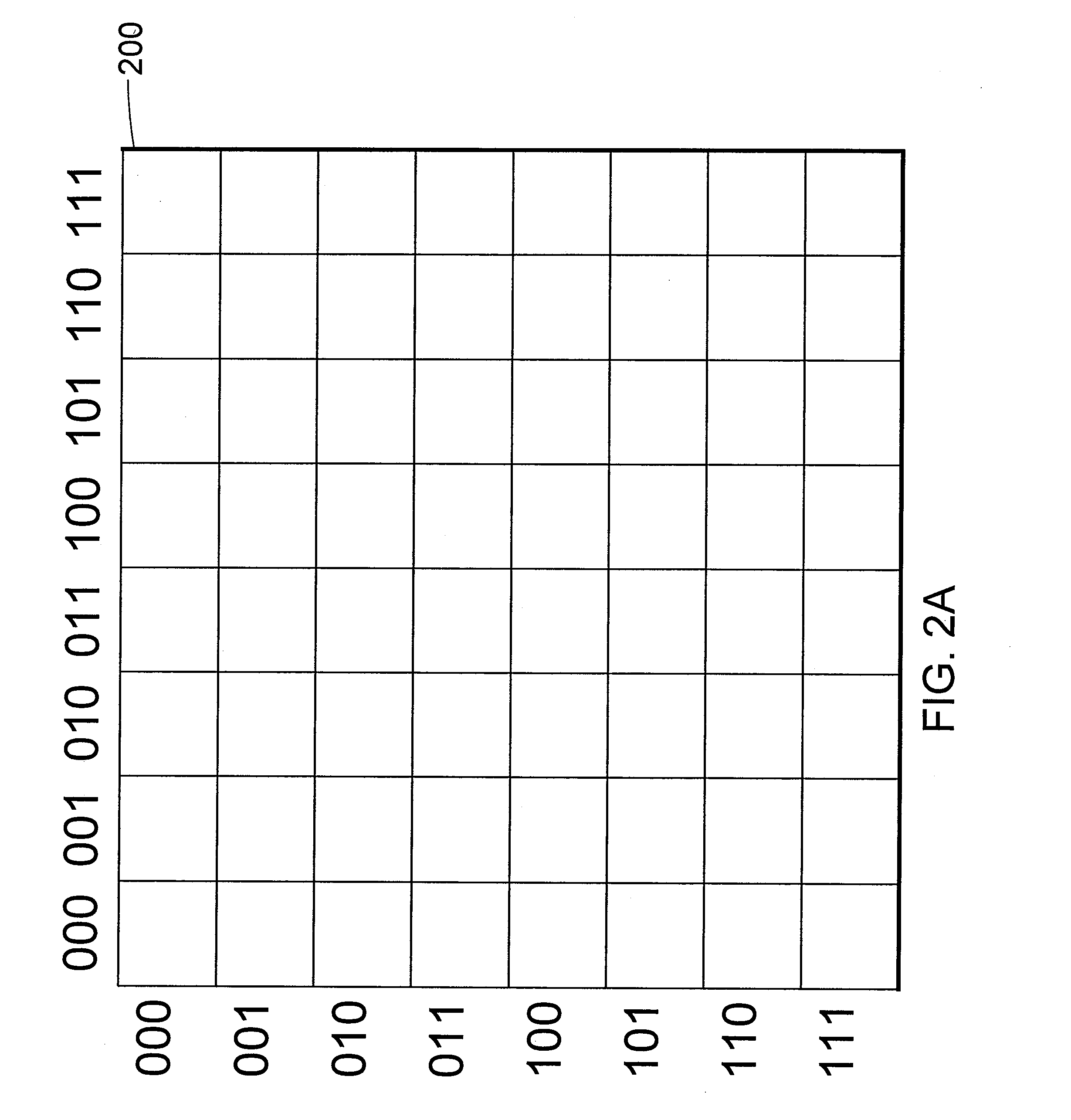
[0042]FIGS. 2A through 2E illustrate the simulation of the folding of a protein according to one embodiment of the present systems, methods and apparatus. In particular, FIGS. 2A through 2E depict the determination of the lowest energy spatial configuration of an arbitrary protein, having a primary structure composed of amino acids S, L, Y and N (primary structure=S-L-Y—N), on a two-dimensional lattice or grid. Those of skill in the art will appreciate that although a two-dimensional lattice has been used for ease of illustration, a lattice of any number of dimensions may be used. In particular, a cubic lattice may be useful for predicting the native structure of a protein having more than two amino acids.

Initialization (Act 110 of FIG. 1)

[0043] The number of amino acids in the subject protein is n=4, therefore, a target graph is created, in this case, a two-dimensional square lattice 200 of side length G=8, as shown in FIG. 2A. Since in this example the protein will be embedded ...

example 2

[0071]FIGS. 3A through 3E illustrate another embodiment of the present systems, methods and apparatus, in which the lowest-energy spatial configuration of the protein of Example 1 (S-L-Y—N) is placed on a smaller target graph. In some cases, a smaller target graph may be desirable, and may allow the use of an analog processor having fewer devices.

[0072] In this example, the target graph 300 that is created is a two-dimensional square lattice of side length G=4, as shown in FIG. 3A. Target graph 300 is smaller than target graph 200 of FIG. 2A since, as will be discussed below, the amino acid selected as the first amino acid to be placed is adjacent to the midpoint of the protein and the amino acid will be placed in the central area of target graph 300. Thus, any possible native structure of the protein can be placed in a square grid having a side length equal to the number of amino acids in the protein.

[0073] Each of the vertical and horizontal axes of target graph 300 are labeled ...


PUM


Abstract

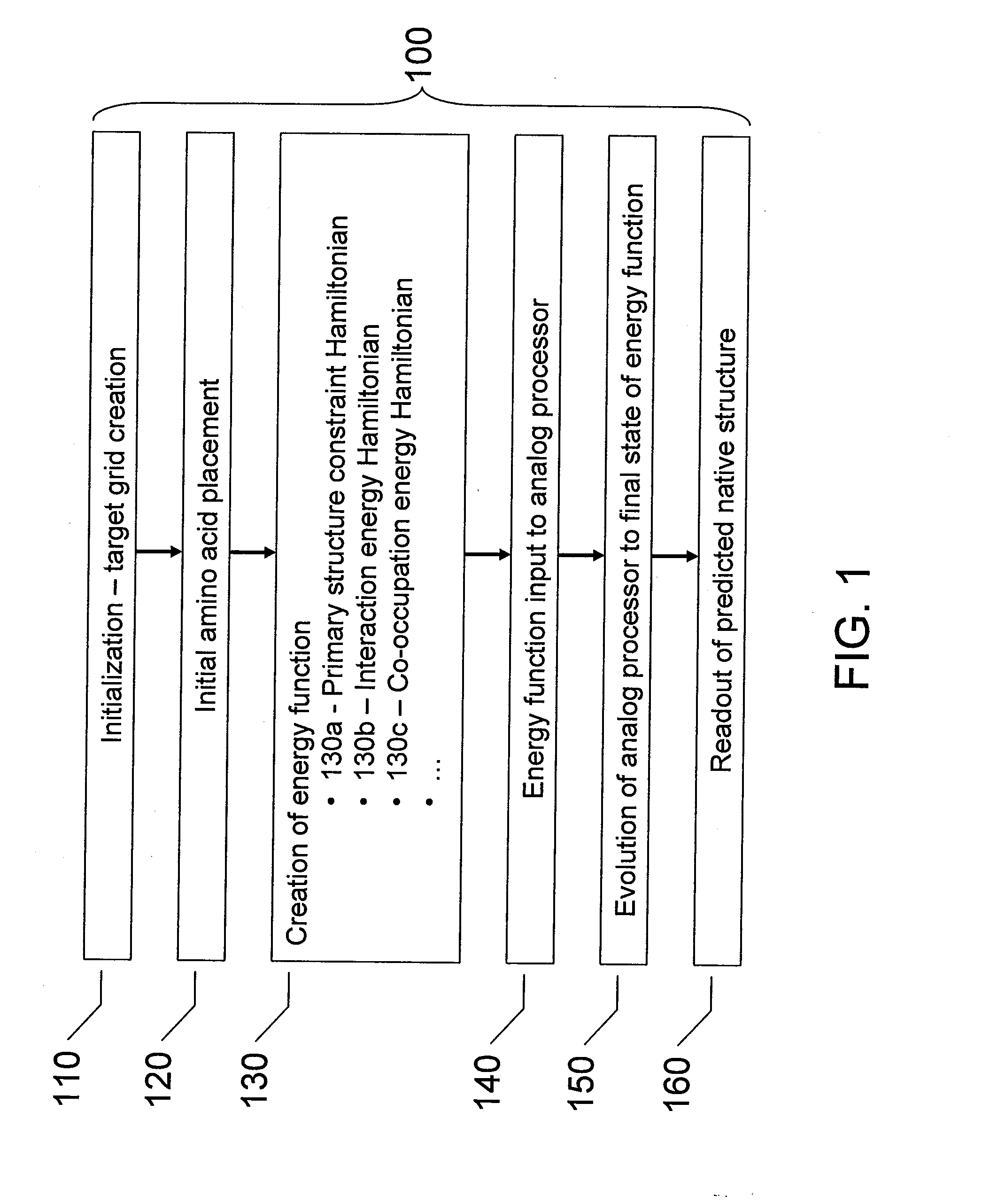
Analog processors such as quantum processors are employed to predict the native structures of proteins based on a primary structure of a protein. A target graph may be created of sufficient size to permit embedding of all possible native multi-dimensional topologies of the protein. At least one location in a target graph may be assigned to represent a respective amino acid forming the protein. An energy function is generated based assigned locations in the target graph. The energy function is mapped onto an analog processor, which is evolved from an initial state to a final state, the final state predicting a native structure of the protein.

Description

CROSS-REFERENCE TO RELATED APPLICATION [0001] This application claims benefit, under 35 U.S.C. §119(e), of U.S. Provisional Patent Application No. 60 / 834,236, filed Jun. 28, 2006, which is incorporated herein, by reference, in its entirety.BACKGROUND OF THE INVENTION [0002] 1. Field of the Invention [0003] The present methods, system and apparatus relate to the simulation of the folding of proteins using an analog processor. [0004] 2. Description of the Related Art [0005] A protein is a polymer composed of a chain of amino acids. The primary structure of a protein is the sequence of amino acids in the chain. Proteins naturally fold into unique three-dimensional structures, known as their “native” state, and it is generally believed that it is the three dimensional shape of the protein that is largely responsible for its biological function. The native structure of a protein is particularly important in fields such as drug discovery, where the native structure can assist in, e.g., ra...

Claims


Application Information

Patent Timeline
IPC IPC(8): G06G7/48G16B15/20
CPCG06F19/16G16B15/00G16B15/20
Inventor ROSE, GEORDIEMACREADY, WILLIAM G.BLOUDOFF, PAUL S.
Owner D WAVE SYSTEMS INC
Learn More