
Intelligent System and Method for Monitoring Generator Reactive Power Limit Using Machine Model Parameters

a technology of intelligent system and machine model, applied in the direction of electric/magnetic computing, analogue processes for specific applications, instruments, etc., can solve the problems of generator reactive power limit, power failure, and conventional techniques cannot meet this requiremen

Inactive Publication Date: 2008-02-28
KOREA ELECTROTECH RES INST
View PDF3 Cites 22 Cited by
  • Summary
  • Abstract
  • Description
  • Claims
  • Application Information

AI Technical Summary

Benefits of technology

[0027]Another object of the present invention is to provide an intelligent system and method for monitoring a generator reactive power limit using machine model parameters, which can estimate and monitor the generator reactive power limit to supply a maximum reactive power or a minimum reactive power to a power system within an allowable generator reactive power limit.
[0028]Yet another object of the present invention is to provide an intelligent system and method for monitoring a generator reactive power limit using machine model parameters to prevent a generator trip due to over-excitation and under-excitation and a large-scale power failure and supply a maximum reactive power to a power system.

Problems solved by technology

A generator reactive power limit is related to voltage stability of a power system.
A large-scale power failure due to an over-excitation trip of a power plant has recently occurred (refer to reference [15]), and there is every possibility that a power failure occurs because of a trip caused by over-excitation or under-excitation of a power plant.
However, conventional techniques cannot meet this requirement.
This method is an approximate technique depending on the capability of the generator operator, and thus it is difficult to estimate a correct generator reactive power operation when power system variables are changed.
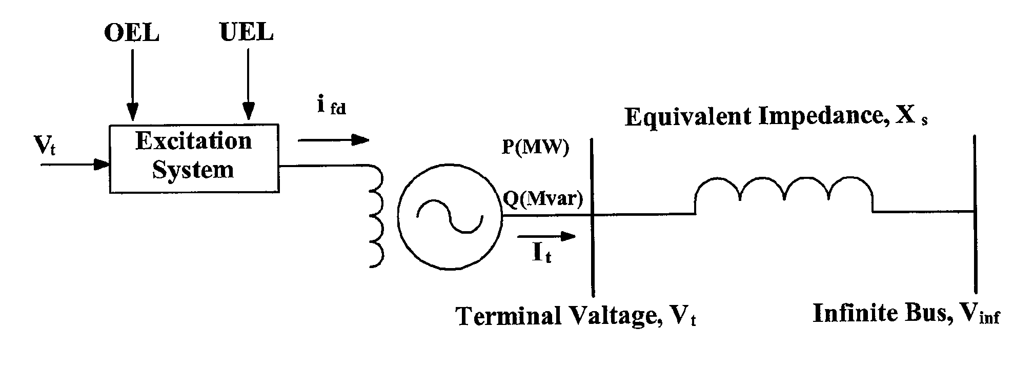
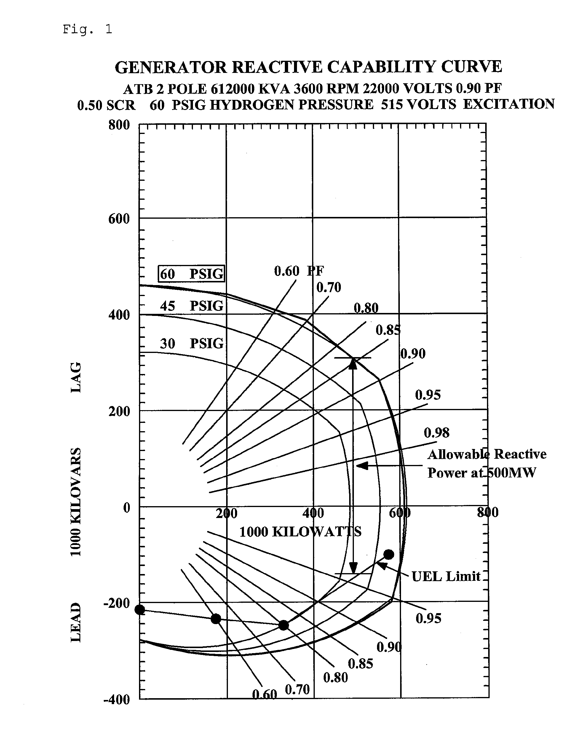
Firstly, it is impossible to calculate a reactive power limit with respect to an OEL generator field current limit and indicate the calculated result on a generator reactive power capability curve. In general, a method of monitoring the reactive power limit of a generator while the generator is operating uses a generator reactive capability curve illustrated in FIG. 1. The generator reactive capability curve illustrated in FIG. 1 indicates an allowable reactive power at 500 MW generator power under 60 PSIG hydrogen pressure. A minimum reactive power limit according to under-excitation can be monitored by indicating an UEL limit on the generator reactive capability curve as illustrated in FIG. 1. In terms of monitoring of a maximum reactive power limit according to over-excitation, however, an OEL limit is set to a generator field current ifd, and thus it is difficult to calculate and indicate a reactive power limit with respect to the OEL generator field current limit. This is because the maximum reactive power limit is varied according to a generator output condition, a terminal voltage and a system voltage. Accordingly, a method of indicating the reactive power limit with respect to the OEL generator field current limit on the capability curve is required.
Secondly, it is impossible to calculate or estimate a terminal voltage corresponding to a reactive power limit with respect to an UEL and indicate the terminal voltage on the capability curve. An UEL limit corresponds to a ratio of a reactive power Qe to an active power Pe, and thus the UEL limit can be indicated on the capability curve as illustrated in FIG. 1. However, the terminal voltage of a generator is important in the actual operation of the generator. The conventional technique has difficulties in calculating or estimating the terminal voltage corresponding to the reactive power limit with respect to the UEL and indicating the terminal voltage on the capability curve.
Thirdly, it is impossible to estimate a variation in power system variables and indicate a maximum generator reactive power limit on the capability curve. A generator is not operated at a single operating point for ceaselessly generating large and small power system disturbances. For example, a generator terminal voltage, a generator active power, a generator reactive power and a network voltage change momentarily. If a generator operator can estimate these power system variables and prepare for a variation in the power system variables, power system reliability is improved. However, there is a limit in this manual method, and thus a method of estimating a variation in the power system variables according to a variation in generator power and automatically indicating the maximum generator reactive power limit on the capability curve is required.
Fourthly, a reactive power limit with respect to a generator over-voltage limit and a generator under-voltage limit cannot be calculated. The generator reactive power limit is affected by the generator over-voltage limit and the under-voltage limit as well as the OEL limit and the UEL limit. Generally, a generator over-voltage and a generator under-voltage are respectively 105% and 95% of a rated voltage. Accordingly, a method of calculating the reactive power limit with respect to the set generator over-voltage limit and the generator under-voltage limit is needed.

Method used


Image

  • Intelligent System and Method for Monitoring Generator Reactive Power Limit Using Machine Model Parameters
  • Intelligent System and Method for Monitoring Generator Reactive Power Limit Using Machine Model Parameters
  • Intelligent System and Method for Monitoring Generator Reactive Power Limit Using Machine Model Parameters

Examples


embodiments

[0078]Hereinafter, results obtained by applying the intelligent system and method for monitoring a generator reactive power limit using machine model parameters according to the present invention to 612 MVA large thermal generator (cylindrical) are described. A rated terminal voltage is 22 kV and a base field current is 1175 Amp. Machine model parameters to be used are verified machine model parameters which correspond to the following measured results. PSS / E power system simulation program is used.

[0079]—Verified Machine Model Parameters

[0080]Table 1 shows a terminal current, an active power, a reactive power, a field current and a load angle which are actually measured. Table 2 shows normal state machine model parameters extracted and verified according to generator testing. Table 3 shows calculation results according to the machine model parameters and measurement results. The field current and the load angle calculated according to the machine model parameters shown in Table 2 n...


PUM


Abstract

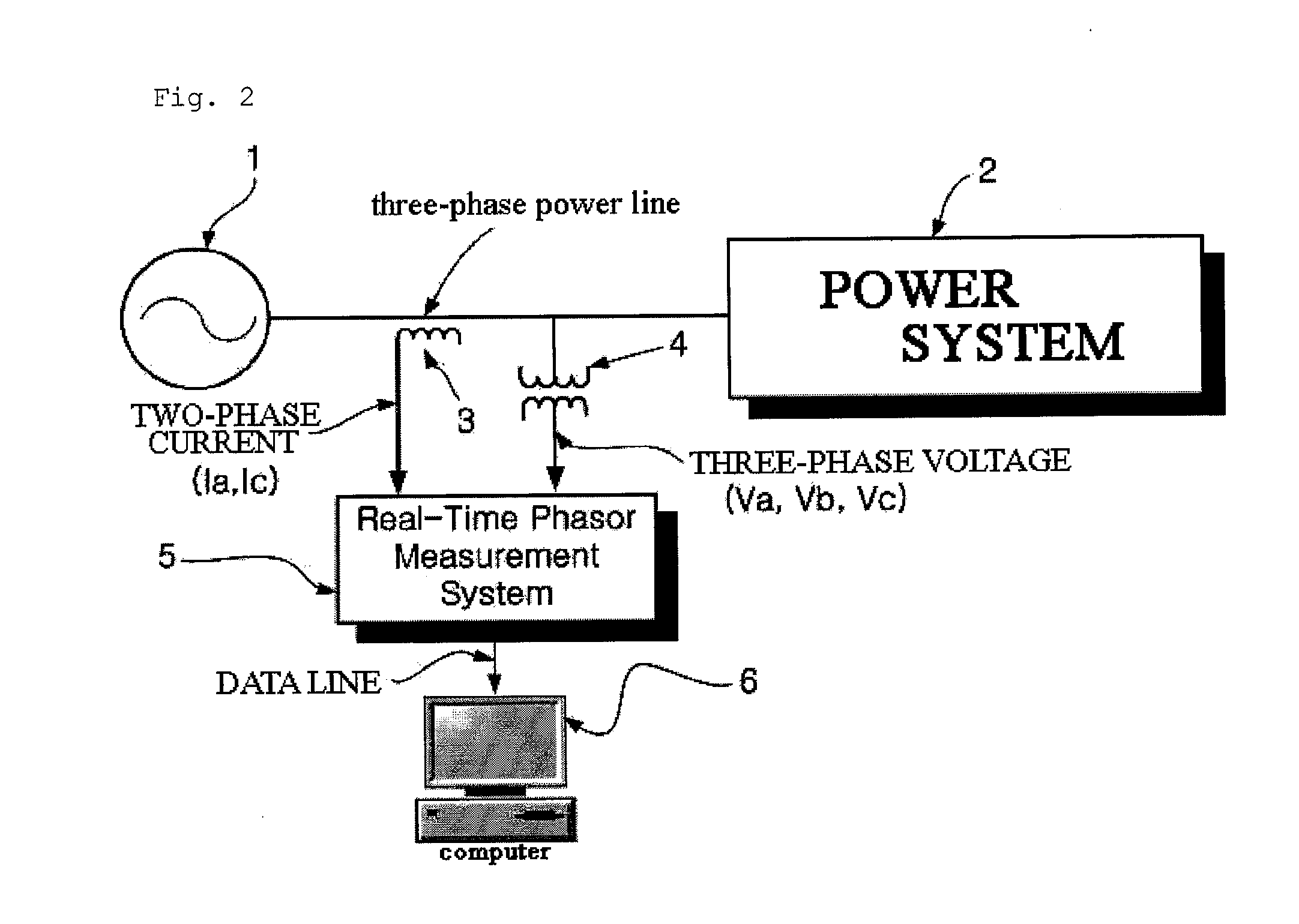
Disclosed herein are an intelligent system and method for monitoring a generator reactive power limit using machine model parameters. The intelligent system and method for monitoring a generator reactive power limit using machine model parameters can calculate a maximum reactive power limit corresponding to over-excitation and a generator terminal voltage corresponding to under-excitation, estimate a correct field current even when system variable are changed, and monitor the generator reactive power limit by using machine model parameters and a one-machine infinite bus, to thereby supply a maximum or minimum reactive power to a power system within an allowable generator reactive power limit and prevent a generator trip caused by the reactive power limit and a power failure over a wide area.

Description

BACKGROUND OF THE INVENTION[0001]1. Field of the Invention[0002]The present invention relates to an intelligent system and method for monitoring a generator reactive power limit using machine model parameters, and more particularly, to an intelligent system and method for monitoring a generator reactive power limit using machine model parameters, which can calculate a maximum reactive power limit corresponding to over-excitation and a generator terminal voltage corresponding to under-excitation, estimate a correct field current even when system variable are changed, and monitor the generator reactive power limit by using machine model parameters and a one-machine infinite bus, to thereby supply a maximum or minimum reactive power to a power system within allowable generator reactive power limit and prevent a generator trip caused by the reactive power limit and a power failure over a wide area.[0003]2. Background of the Related Art[0004]References for the present invention are as fo...

Claims


Application Information

Patent Timeline
Patent Type & Authority Applications(United States)
IPC IPC(8): G06F19/00
CPCG01R31/343Y02E60/7807Y04S40/12H02J13/0017H02J13/00006Y02E60/00G01R31/34
Inventor KIM, DONG JOONMOON, YOUNG HWANYOON, JAE YOUNG
Owner KOREA ELECTROTECH RES INST
Learn More