Firearm Grip with Rest

a technology for firearms and grips, applied in the field of firearm grips, can solve the problems of increasing shooting difficulty, structural damage in the long term, and still being rather inconvenient and laborious, and achieve the effects of preventing frostbite, poor heat conductivity, and reducing heat conduction

Inactive Publication Date: 2008-03-06
LEE SHANYAO
View PDF25 Cites 96 Cited by
  • Summary
  • Abstract
  • Description
  • Claims
  • Application Information

AI Technical Summary

Benefits of technology

[0025]Compared to the conventional single-body grip configuration that conducts heat quickly to the user, the firearm grip with a rest as in the present invention comprises a shell with poor heat conductivity for encasing the grip body made of aluminum to reduce heat conduction as well as prevent frostbite when used in a cold environment. Besides, the shell can be designed to have a shape that is easy to be gripped by the user.
[0026]Furthermore, although the grip of the prior art may have an automatically projected bipod controlled by a button, however this type of configuration may easily be triggered by an accident or unintentionally pressing the button, and its internal structural is prone to wear out over time, gradually losing its functionality for engaging the bipod such that the projection of the bipod becomes even more easily triggered unintentionally. In comparison, for the firearm grip with a rest as in the present invention, when the rest is not in use, the rest is received in the grip body and is prevented from falling out of the grip body by means of the elastic member. Even if elastic fatigue of the elastic member occurs, the user can easily find out the problem and replace the elastic member.
[0027]In addition, the bipod of the conventional grip cannot be easily and quickly retracted into the grip pod, whereas the firearm grip with a rest as in the present invention allows the rest to be quickly and easily retracted into the grip body via the elasticity of the elastic member. In another embodiment, the rest of the firearm grip of the present invention is rotatably retracted into the grip body, which does not require the user to apply force against the elasticity of the spring as in the prior art, such that the rest can be retracted without strenuous effort that may cause structural damage.

Problems solved by technology

This is very inconvenient especially when the user is carrying out a sniping task.
As such, the position for the user's hand to exert force on the firearm and the position of the bipod 1 supporting the firearm are different, thereby easily causing torque and increasing shooting difficulty.
The user has to overcome the elasticity between the legs 210, 211 and the elasticity of the spring exerted on the bipod 21; this is still rather inconvenient and laborious.
It may possibly occur that the user retracts the bipod 21 into the grip pod 2 with too much force, causing structural damage in the long term.
Moreover, although the bipod that can be quickly projected out of the grip pod 2 allows the user to get in a shooting position quickly, which satisfies the requirement for an infantry to quickly get in a fighting position, however when changing the shooting position, it requires certain effort to retract the bipod into the grip pod, which does not satisfy the tactics of immediately changing a position after sniping.
Furthermore, the titling angle of the firearm combined to the grip pod 2 cannot be adjusted.
Additionally, the engaging mechanism inside the grip pod 2 for engaging the bipod 21 may wear out over time due to friction, such that the bipod 21 may be easily projected due to vibration or dropping of the firearm.
When the temperature exceeds the user's tolerance, it would affect the performance of shooting.
Similarly, when the grip pod 2 is used at a cold area, such as a high altitude or high elevation area, the surface of the metal may easily be frosted, which if touched by bare hands may possibly result in frostbite or sticking of the hand.

Method used


Image

  • Firearm Grip with Rest
  • Firearm Grip with Rest
  • Firearm Grip with Rest

Examples


first embodiment

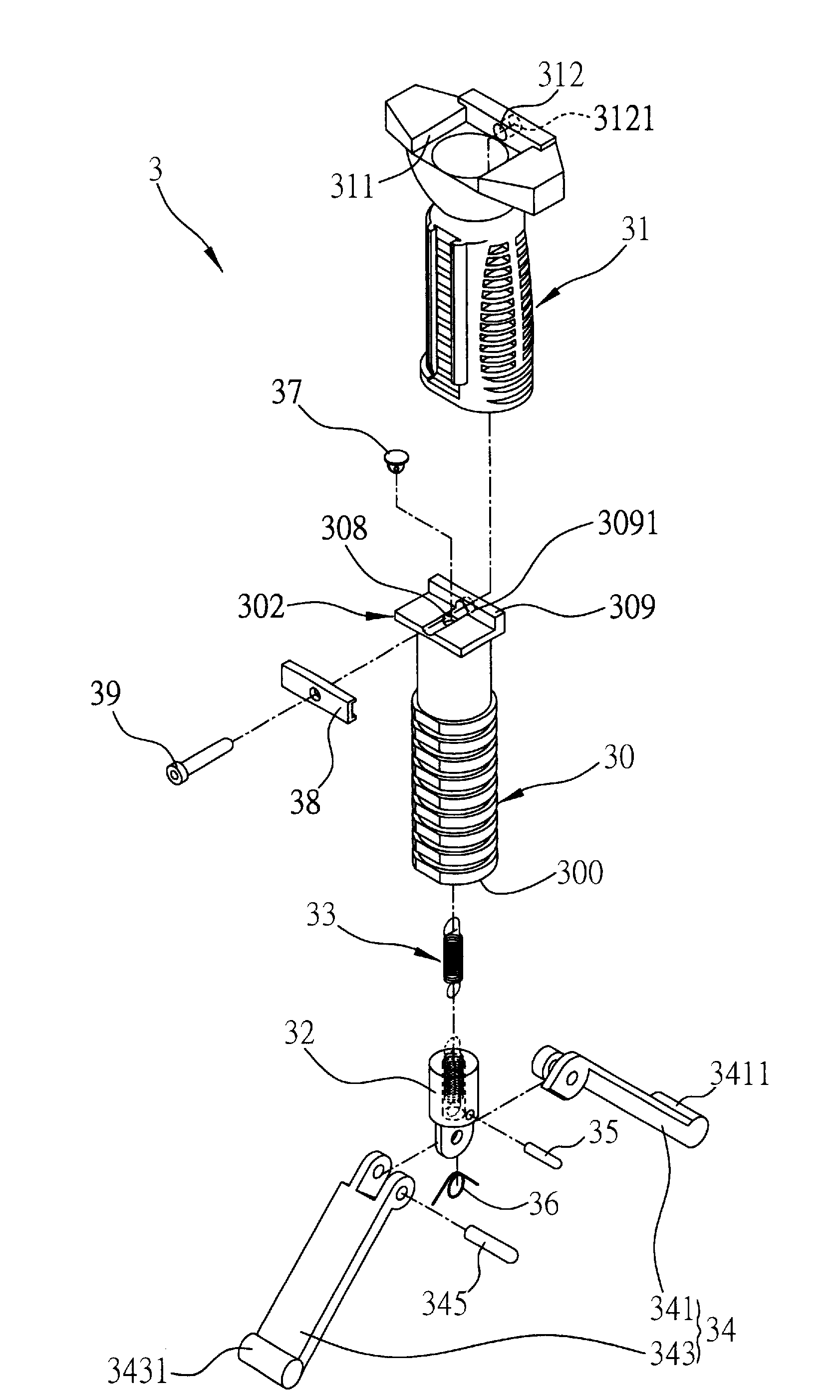
[0044]Referring to FIG. 3A, a schematic diagram of a firearm grip with a rest according to a first embodiment of the present invention is shown. The firearm grip 3 of the present invention comprises: a grip body 30 having a hollow portion; a shell 31 for enclosing and combined with an outside of the grip body 30 and exposing a bottom 300 of the grip body 30; a rest received in the grip body 30 and capable of being projected from the bottom 300 of the grip body 30 to position the firearm grip 3 on a setting surface (not shown); and an elastic member 33 for connecting the grip body 300 and the rest and for providing elasticity to retract the rest into the grip body 30.

[0045]The material of the grip body 30 is aluminum alloy. The shell 31 is a rubber, plastic or heat-insulating shell to insulate the grip body 30 again heat conducted from the barrel during shooting. Additionally, the shell 31 can be formed as an ergonomic shape that facilitates gripping of the shell 31 by a user.

[0046]A...

second embodiment

[0054]Referring to FIGS. 4A to 4C, a firearm grip with a rest according to a second embodiment of the present invention is shown.

[0055]As shown in FIG. 4A, the second embodiment is similar to the first embodiment, with differences in that in the second embodiment, the rest is a column 41 with a combining portion 411 formed on a top surface thereof, such that the rest is coupled to an end of the elastic member 43 via the combining portion 411, wherein the combining portion 411 may for example be hollow and is coupled to the end of the elastic member 43 by a laterally disposed rod 42.

[0056]Additionally, a protrusion 412 can be provided at the bottom of the column 41, for being inserted in soft ground. The protrusion 412 may also function as a pivot point when adjusting the shooting direction of the barrel. A protruding step 413 can also be formed on the bottom of the column 41 so as to be blocked at the bottom 400 of the grip body 40 when the column 41 is received in the grip body 40,...

third embodiment

[0059]Referring to FIG. 5A, a firearm grip with a rest according to a third embodiment of the present invention is shown.

[0060]The third embodiment is a modification of the second embodiment, with differences in that in the third embodiment, the rest is a column 53, the top of which is coupled to an end of the elastic member 54. More specifically, a dent 530 is formed on the top of the column 53 such that a rod 52 can be laterally disposed in the dent 530 to couple the column 53 to the end of the elastic member 54.

[0061]An elastic operating member 51 is provided on the bottom of the grip body 50. The elastic operating member 51 comprises a first engaging part 510 extended into the grip body 50, and a second engaging part 531 is provided on a side of the column 53 and corresponds to the first engaging part 510. The column 53 can be received in or projected from the grip body 50 according to an engagement between the first engaging part 510 and the second engaging part 531. The engage...


PUM


Abstract

A firearm grip with a rest is provided, which at least has a grip body with a hollow portion, a shell encasing and combined with an outside of the grip body and exposing a bottom of the grip body, and a rest received in the grip body and capable of being projected from the bottom of the grip body to position and support the firearm grip against a setting surface. The grip body and the rest can be coupled to each other by an elastic member that allows the rest to be resiliently retracted back into the grip body. Alternatively, the rest can be pivotally coupled to the grip body and rotatably retracted into the grip body. The above firearm grip eliminates the shortcomings of the prior art.

Description

FIELD OF THE INVENTION[0001]The present invention relates to firearm grips, and more particularly, to a firearm grip with a rest.BACKGROUND OF THE INVENTION[0002]Generally, when rifles are used for long-range shooting, supporting structures are needed for precise shooting in addition to optical sights.[0003]Referring to FIG. 1, U.S. Pat. No. 6,763,627 discloses a bipod. The bipod 1 comprises a supporting body 10; a yoke 12 rotatably combined with the supporting body 10 to hold a barrel; and two legs 11a, 11b that can be stretched open or close. A user is able to fix a firearm by the yoke 12 holding the barrel in place and the two legs supporting the barrel while shooting so as to make the shooting more precise.[0004]However, the bipod 1 disclosed in the above prior art requires the user to manually stretch open or close the two legs when the bipod 1 is in use or not in use. This is very inconvenient especially when the user is carrying out a sniping task. Moreover, the bipod 1 merel...

Claims


Application Information

Patent Timeline
Patent Type & Authority Applications(United States)
IPC IPC(8): F41C27/00
CPCF41A23/04F41C23/16F41A23/08
Inventor LEE, SHANYAOLEE, HUI-CHIH
Owner LEE SHANYAO
Why Eureka
Try Eureka