
Gasoline and diesel production from pyrolytic lignin produced from pyrolysis of cellulosic waste

a technology of pyrolysis and cellulosic waste, which is applied in the direction of hydrocarbon oil cracking, bio-feedstock, fuels, etc., can solve the problems of uneconomical and difficult direct use of pyrolysis oil, and achieve the effect of high yield

Inactive Publication Date: 2008-03-06
UOP LLC
View PDF2 Cites 95 Cited by
  • Summary
  • Abstract
  • Description
  • Claims
  • Application Information

AI Technical Summary

Benefits of technology

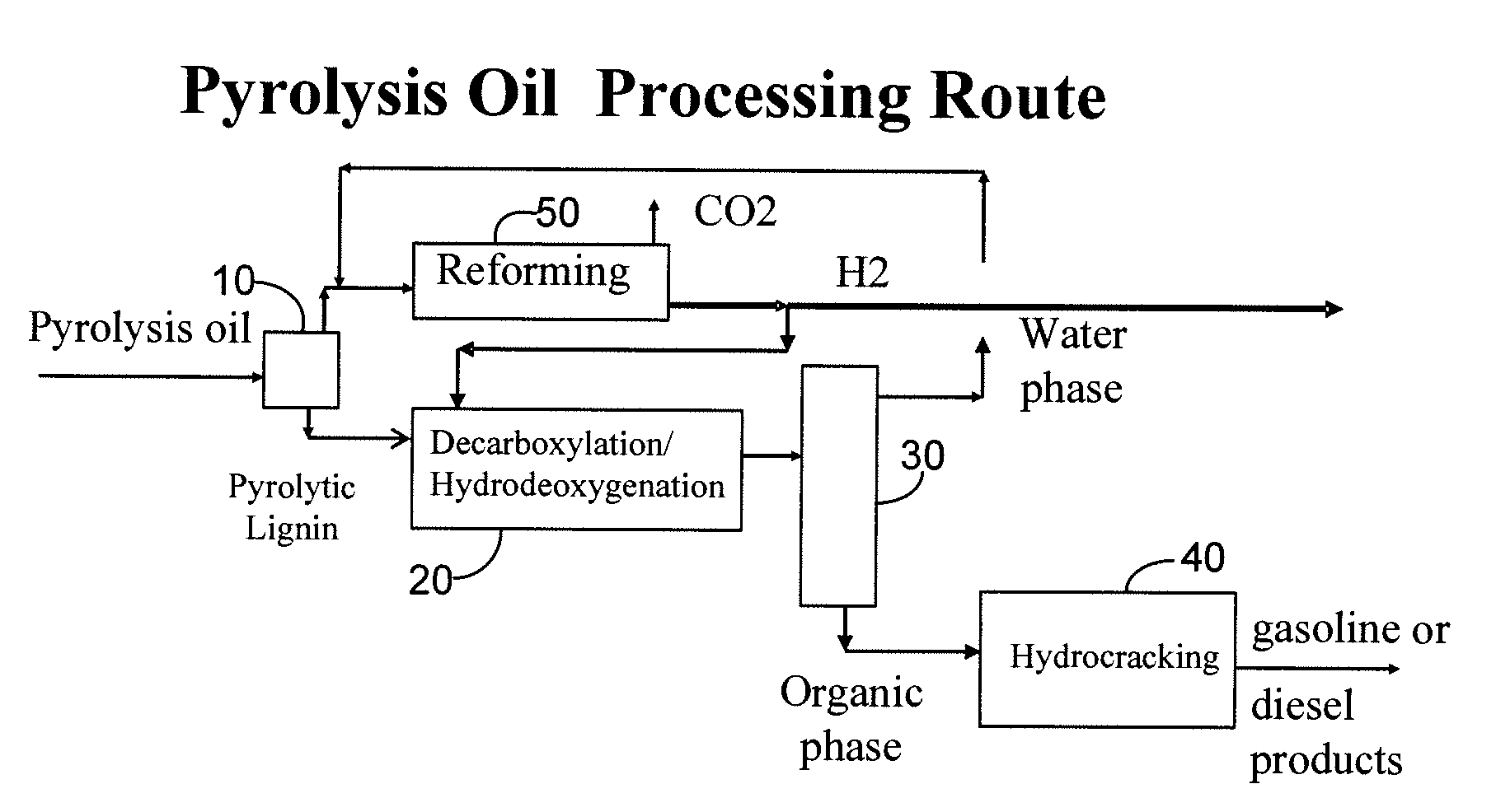
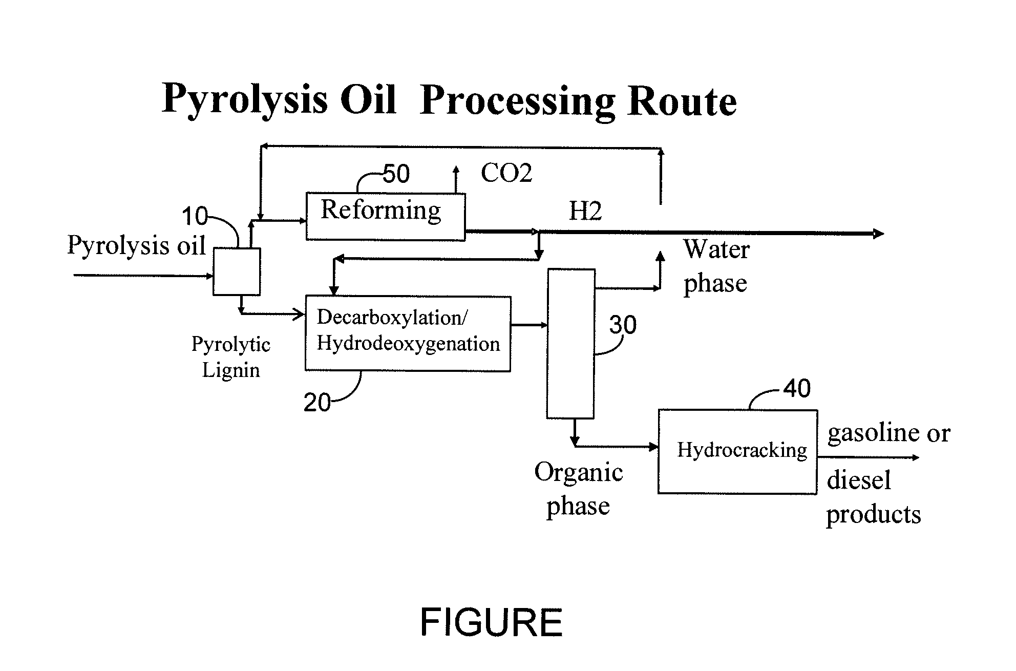
The invention is a process that can make high yields of fuel from biomass. It involves separating the oil from the biomass and treating it to remove some of the oxygen. This treated oil is then further treated to produce a hydrocarbon product stream that can be used as gasoline and naphtha. The process is efficient and can produce a high yield of useful fuel from biomass.

Problems solved by technology

This patented technical problem addressed by this patent relates to finding ways to utilizing bio-based materials like biodiesel produced during production rather than relying solely upon importation. Additionally, it addresses how to dispose of these wastes safely through various methods, including burning them at high temperatures near their end points instead of being sent away after they have been create.

Method used


Image

  • Gasoline and diesel production from pyrolytic lignin produced from pyrolysis of cellulosic waste
  • Gasoline and diesel production from pyrolytic lignin produced from pyrolysis of cellulosic waste

Examples


example

[0021]The pyrolysis oil was separated into two streams before hydrotreating the pyrolytic lignin, a pyrolytic lignin stream and a water soluble pyrolysis oil phase stream. The separation was performed using two methods, a water precipitation method and a density method. The pyrolytic lignin has an enriched carbon content and a reduced oxygen content relative to the pyrolysis oil before separation, as shown in Table 1. The amount of pyrolytic lignin that is recoverable from the pyrolysis oil before hydrotreating is about 30% by weight of the pyrolysis oil. Different separation methods can yield slightly different results. The elemental analyses in Table 1 are shown on a moisture free basis as indicated by “mf”.

TABLE 1PyrolysisPyrolyticWater SolublePyrolyticWater SolubleOilLigninPyrolysis OilLigninPyrolysis OilWeight %10027733268SeparationWaterWaterDensityDensitymethodprecipitationprecipitation% C mf44.76935.862.336.5% H mf7.26.97.36.97.3% N mf0.20.30.20.30.2% O mf47.923.856.730.556.0...


PUM


Abstract

A process for the conversion of biomass to a liquid fuel is presented. The process includes the production of diesel and naphtha boiling point range fuels by hydrocracking of pyrolysis lignin extracted from biomass.

Description


Claims


Application Information

Patent Timeline
Owner UOP LLC
Learn More