Wall Smoothness, Feature Accuracy and Resolution In Projected Images Via Exposure Levels In Solid Imaging

a technology of exposure level and projection image, which is applied in the direction of process and machine control, process control, instruments, etc., can solve the problems of shrinkage, resolution, accuracy, and difficulty, and achieve the effect of low cost, accurate features and good resolution

Active Publication Date: 2008-03-06
3D SYST INC
View PDF48 Cites 87 Cited by
  • Summary
  • Abstract
  • Description
  • Claims
  • Application Information

AI Technical Summary

Benefits of technology

[0015]It is an advantage of the present invention that a low cost solid imaging device is obtained that provides smooth object edges in the projected image along with accurate features and good resolution without the need for additional mechanical hardware.
[0016]It is another advantage of the present invention that accurate feature placement in each cross-section in a three-dimensional object being built layer-by-layer is obtained so that accurate feature placement is not lost due to the fixed number of pixels that can be projected in a single image projection by a digital light projector.
[0017]It is still another advantage of the present invention that a digital light projector can be characterized for light intensity width in both the X and Y directions as a function of the pixel location to achieve smooth image edges and less image granularity with enhanced image resolution.
[0018]These and other aspects, features, and advantages are obtained by the present invention through the use of a solid imaging apparatus and method that employ gray scale exposure levels for the boundary pixels in an image area of a cross-section and software that determines the gray scale exposure levels for the boundary pixels across the image projected by a digital light projector onto a solidifiable photopolymer build material in order to optimize the projected image by a projector that is characterized for light intensity width and light intensity versus gray scale controlling the polymerization boundary of the solidifiable photopolymer build material in the boundary pixels forming an object edge or wall to enable a three-dimensional object to be built with no lost features or uneven or rough edges, while retaining high resolution.

Problems solved by technology

Such systems have encountered and had to overcome difficulties relating to shrinkage, curl and other distortions, as well as resolution, accuracy, and difficulties in producing certain object shapes.
Digital light projectors typically project only 100 pixels per inch for an image size of 10.24 inches by 7.68 inches, so their resolution is limited by the pixel sizes.
Attempting to utilize image displacement techniques with digital image projections in solid imaging applications presents unique problems because of the three-dimensional aspect of the object being created.
The problems of two-dimensional digital image projection, when applied to three-dimensional solid imaging, cause inaccurate feature placement, potential loss of feature details, and smoothness of curves or edges on objects being built to be roughened or uneven and poorly defined.
However, those approaches suffer from the deficiencies of requiring multiple exposures of individual pixels, thereby inherently slowing the process, and requiring mechanical hardware to accomplish the pixel shifting.
Additionally, when using multiple exposures with techniques such as pixel shifting, there are alignment issues that must be addressed to ensure the exposures are properly positioned to obtain maximum resolution and the desired edge smoothness.
Lastly, none of the prior solid freeform fabrication approaches, while making substantial improvements, achieve a truly low cost system that produces highly accurate and visually appealing three-dimensional objects in a short build time.

Method used


Image

  • Wall Smoothness, Feature Accuracy and Resolution In Projected Images Via Exposure Levels In Solid Imaging
  • Wall Smoothness, Feature Accuracy and Resolution In Projected Images Via Exposure Levels In Solid Imaging
  • Wall Smoothness, Feature Accuracy and Resolution In Projected Images Via Exposure Levels In Solid Imaging

Examples


Embodiment Construction

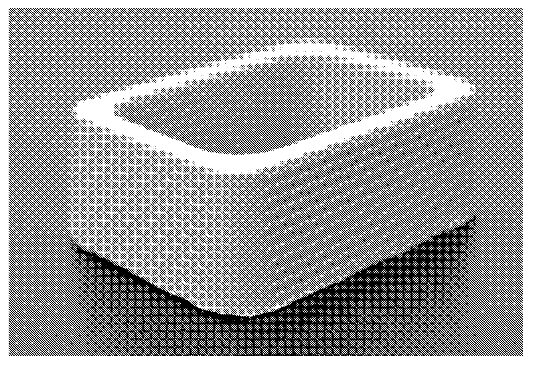
[0035]The preferred flexible transport solid imaging of the type disclosed herein involves the layer-by-layer build-up of articles from a visible or UV solidifiable photopolymer build material that is delivered by a radiation transparent flexible carrier, such as an endless belt or reciprocating or extendable and retractable sheet of transparent plastic film. The term “transparent” as used in this context means any suitable material that allows the passage of sufficient radiation (such as UV or visible light) through it to effect the photopolymerization reaction. Because these transparent materials may be very thin, the term would also include translucent or partially transparent materials. The radiation transparent flexible carrier works as a recoater that delivers fresh solidifiable photopolymer build material to the imaging area for subsequent layers that are formed after the initial layer. Solidifiable photopolymer build material is applied to the radiation transparent flexible ...


PUM

PropertyMeasurementUnit
sizesaaaaaaaaaa
sizesaaaaaaaaaa
roughnessaaaaaaaaaa

Abstract

A solid imaging apparatus and method employing levels of exposure varied with gray scale or time or both of digitally light projected image of a cross-section of a three-dimensional object on a solidifiable photopolymer build material. The gray scale levels of exposure of projected pixels permits the polymerization boundaries in projected boundary pixels to be controlled to achieve preserved image features in a three-dimensional object and smooth out rough or uneven edges that would otherwise occur using digital light projectors that are limited by the number of pixels in an image projected over the size of the image. Software is used to control intensity parameters applied to pixels to be illuminated in the image projected in the cross-section being exposed in the image plane.

Description

FIELD OF INVENTION[0001]The present invention is directed to a technique to achieve improved wall smoothness and feature accuracy in an image projection system limited by the projected size of the pixels, such as occurs with light valve projectors using DMD or LCD based projectors, for use in an apparatus for forming three-dimensional objects on a layer-by-layer basis. More particularly, it is directed to an apparatus and method for forming three-dimensional objects using exposure levels varied with gray scale or time or both in a projected image to obtain enhanced smoothness in the x, y-plane and on the z-axis edge, feature accuracy, and better resolution in the three-dimensional object being formed from a solidifiable photopolymerizable medium in response to exposure by UV or visible light.BACKGROUND OF THE INVENTION[0002]In recent years, many different techniques for the fast production of three-dimensional models have been developed for industrial use. These solid imaging techni...

Claims


Application Information

Patent Timeline
Patent Type & Authority Applications(United States)
IPC IPC(8): B29C35/08B29C41/02
CPCB29C67/0066B29K2995/0073B29C67/0088B29C64/135B29C64/40B33Y30/00B33Y70/00B33Y80/00B29C64/393B33Y50/02G05B19/4099G05B2219/49019
Inventor KEREKES, THOMAS ALANPARTANEN, JOUNI P.CHEN, YONGHULL, CHARLES W.
Owner 3D SYST INC
Why Eureka
Try Eureka