Oscillator coil geometry for radio frequency metal detectors

a technology of oscillator coil and metal detector, which is applied in the field of radio frequency metal detection, can solve the problems of reducing detector performance and raising background noise, and achieve the effects of reducing the size of the smallest detectable contaminant, enhancing the received signal level, and reducing the size of the search head

Inactive Publication Date: 2008-03-06
BRITTON ANDREW MICHAEL
View PDF9 Cites 12 Cited by
  • Summary
  • Abstract
  • Description
  • Claims
  • Application Information

AI Technical Summary

Benefits of technology

[0018]In other embodiments of the present invention, relatively larger search heads a combination of both series interconnected and parallel interconnected can be used together to increase received signal levels. Relatively smaller search heads can be enhanced by the use. of multiple sets of series interconnected coils.
[0019]All of the techniques of the present invention together produce cumulative improvements in the resultant metal detecting apparatus. For example, the use of...

Problems solved by technology

The current is typically so high, in fact, that the voltage must be reduced to prevent the coil current from exceeding a...

Method used


Image

  • Oscillator coil geometry for radio frequency metal detectors
  • Oscillator coil geometry for radio frequency metal detectors
  • Oscillator coil geometry for radio frequency metal detectors

Examples


Embodiment Construction

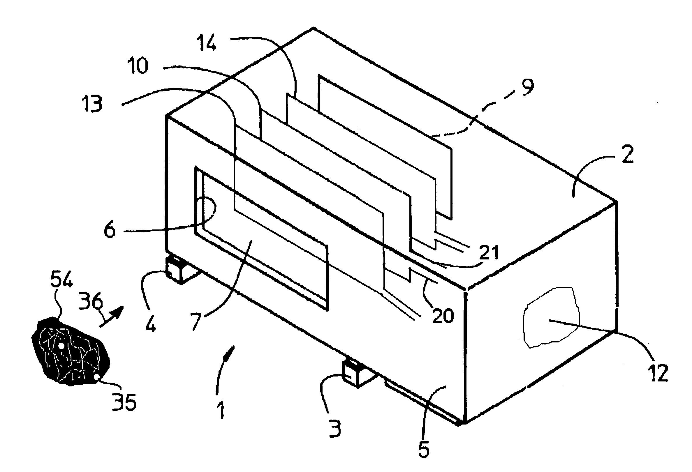
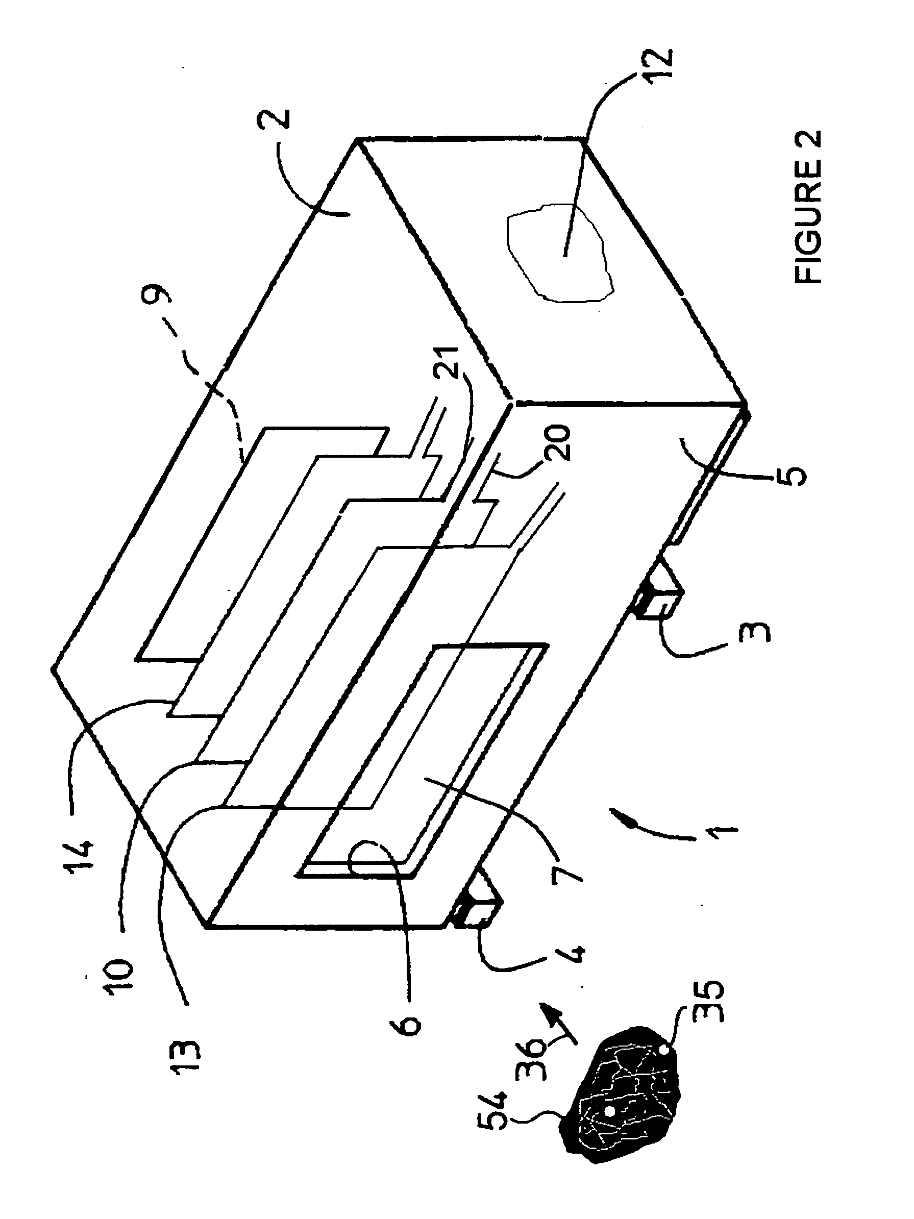
[0030]Referring to FIG. 2, a metal detector constructed according to the principles of the present invention is shown generally at 1. The metal detector 1 includes a metal or conductive cabinet 2, typically stainless steel or aluminum that is supported by shock absorbing feet 3 and 4. The cabinet is formed to include a generally rectangular first sidewall 5. The sidewall 5 includes an opening or first aperture 6 which permits access to the interior volume of cavity 7. The cavity 7 is bounded by a coaxially aligned second aperture 9, such that an article 54 may enter the cavity 7 through first aperture 6 and exit cavity 7 through the second aperture 9. The article may enter the cavity 7 by traveling generally in the direction of arrow 36 via a conveyor which may be a belt or chain as well as gravity feed mechanism or a pump forwarding the article through a conduit. In an alternate embodiment the aperture may have a circular shape, and the entire cabinet may also be generally circular...


PUM


Abstract

A metal detector (1) used for identifying contaminants (35) in products (35). The detector (1) includes an oscillator coil assembly (10) that may be formed as a combination of pairs of series wound coils (15, 18) and pairs of parallel wound coils (16, 17). A pair of input coils (13, 14) defines the boundaries of a region (39) within which the oscillator coil assembly (10) resides. A first signal (8) is generated by the first input coil (13) in response to the presence of a metallic object (35) while a second signal (24) is generated by the second input coil (14) in response to the presence of the metallic object (35). By measuring the ratio of the first signal (8) to the second signal (24) the physical location of a metal object within the metal detector cavity (7) can be determined.

Description

BACKGROUND OF THE INVENTION[0001]1. Field of Invention[0002]This invention pertains generally to the field of radio frequency metal detection, and more particularly to improving the flux density of the magnetic field used in such a device.[0003]2. Description of Prior Art[0004]Metal detectors are used in the food processing industry, for example, to detect contaminants within a product. The unwanted material may include very small metallic particles having differing compositions. The typical metal detector is housed in an enclosure containing a longitudinal aperture through which the product under test is transported, usually by means of a conveyor belt. The metal detector includes a radio frequency transducer or oscillator that radiates a magnetic field by means of some arrangement of coils that serve as a radio frequency antenna.[0005]The typical metal detector includes a search head which contains both radiating and receiving coils, the search head being formed to surround the ap...

Claims


Application Information

Patent Timeline
IPC IPC(8): G08B13/24G01V3/08
CPCG01V3/107
Inventor BRITTON, ANDREW MICHAEL
Owner BRITTON ANDREW MICHAEL
Why Eureka
Try Eureka