
Shield for radio frequency ID tag or contactless smart card

Inactive Publication Date: 2008-03-06
EXPONENT
View PDF12 Cites 59 Cited by
  • Summary
  • Abstract
  • Description
  • Claims
  • Application Information

AI Technical Summary

Benefits of technology

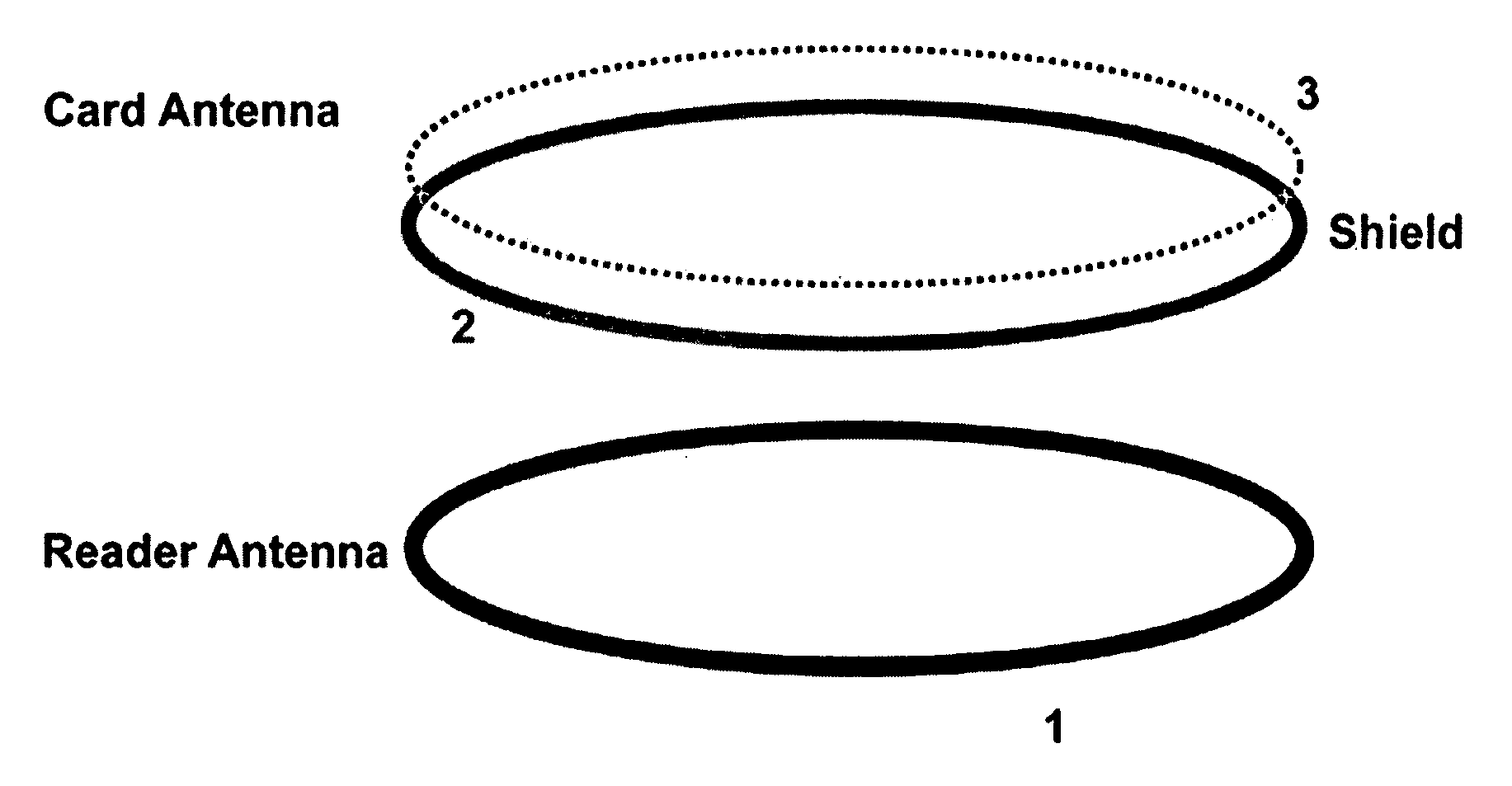
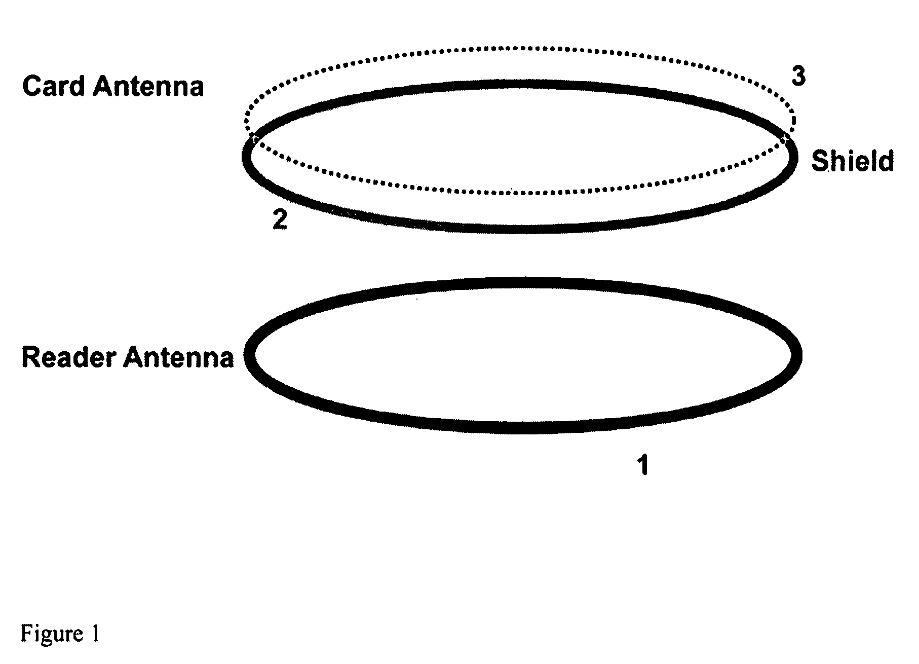
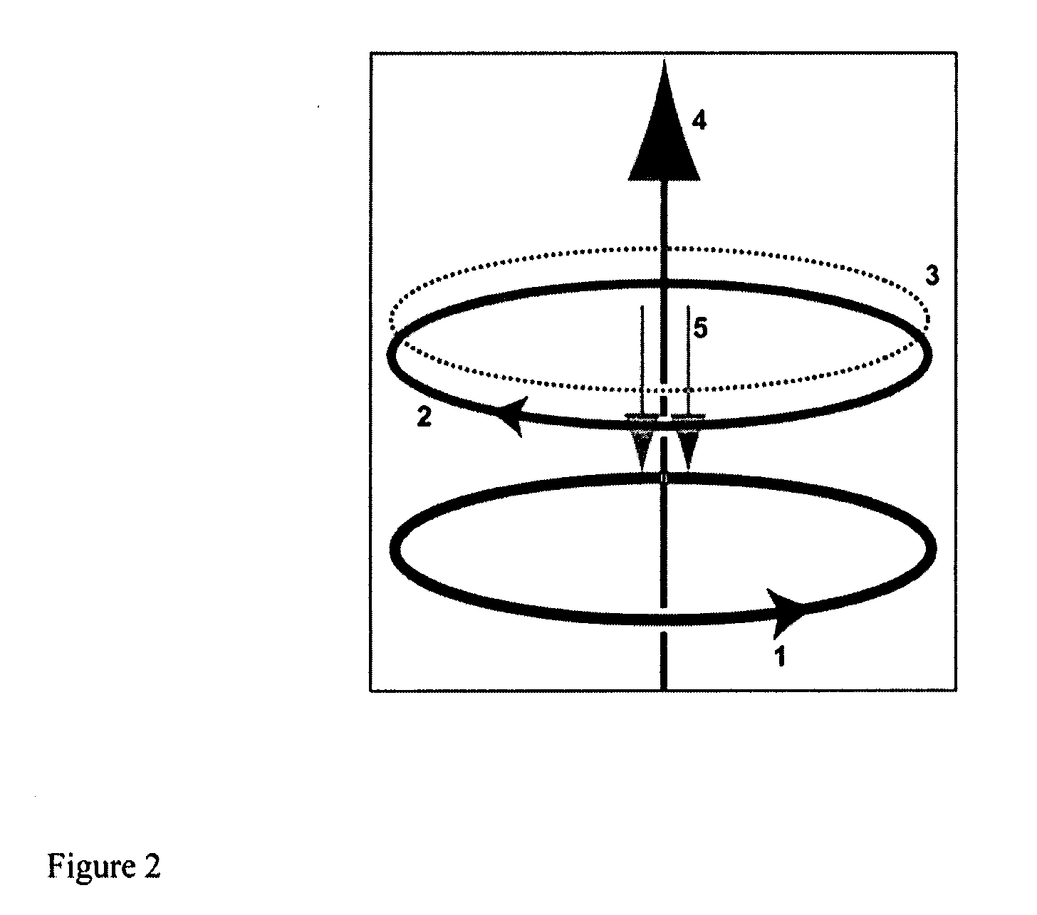
[0014]We have found that for inductively coupled RFID systems, the shield does not have to be present on all the sides of the device. It is also not required that one side be covered completely. In fact, a shield of any shape that allows a current to flow in a closed loop may be enough to shield the RFID. The only requirement is that the back electromagnetic field (EMF) from the shield induces sufficient flux to cancel all or part of the magnetic flux coming from the reader. It is possible for the shield to work even if the induced flux is small: the shift in the self-inductance of the RFID or contactless card coil due to the presence of the material in the shield can be enough to cause a shift in a resonant frequency of the circuit and thus in the power delivered to the chip.
[0016]An additional advantage of a non-contiguous shielding means is that it offers the possibility of controlling how and whether the electrical current path is open or closed; this, in turn, dictates whether or not the shield is preventing a RFID tag, contactless smartcard, or other RFID device from being read. This allows the advantage of easily enabling or disabling the reading ability of RFID devices, even without removing the devices from the shield. Thus, the card is read only when required, and yet protected at other times. The control to open or close the shielding means can be mechanical, electrical, or optical. Additionally, such controls do not necessarily require user intervention. For example, a light shining on an integrated photodiode in the RFID shield can open the electrical circuit and prevent the current from flowing in the shield. Then the card can be read until the light is turned off or blocked or the card is separated from the shield. Additionally, a “virtual shield” can be implemented by moving optical sensor into the card itself as specified in Detailed Description of the Invention.

Problems solved by technology

First, the reader powers the embedded electronic means such as a RFID chip via a high rate of change of magnetic field (flux) through the card coil.

Method used


Image

  • Shield for radio frequency ID tag or contactless smart card
  • Shield for radio frequency ID tag or contactless smart card
  • Shield for radio frequency ID tag or contactless smart card

Examples


Embodiment Construction

[0021]The use of a shield to modify the mutual inductance of the reader and the card and / or self-inductance of the card antenna allows for a shield design that can be tailored closely to requirements of multiple applications. This invention can be used to design a physical shield for “smart” contactless ID badges that are meant to both be read by a remote transceiver as well as be displayed visibly while inside the holder. Several different embodiments of a badge holder have been implemented and tested with cards that adhered to ISO / IEC7810 standard.

[0022]Although other materials can be used, aluminum is an inexpensive effective shielding material that can completely block a standard smartcard reader (for example Model SDO10, 13.56 MHz card readers sold by SCM Microsystems) when covering one side of a typical contactless smartcard. Even when a 2.5 cm strip along the side of the smartcard is exposed, a shield covering the remaining portion has been shown to reduce the distance at whi...


PUM


Abstract

We have found that to effectively shield inductively coupled RFID systems, the shield does not have to be present on all the sides of the device. It is also not required that one side be covered completely. In fact, a shield of any shape that allows a current to flow in a closed loop may be enough to shield the RFID. The only requirement is that the back electromagnetic field (EMF) from the shield induces sufficient flux to cancel all or part of the magnetic flux coming from the reader. It is possible for the shield to work even if the induced flux is small: the shift in the self-inductance of the RFID or contactless card coil due to the presence of the material in the shield can be enough to cause a shift in a resonant frequency of the circuit and thus in the power delivered to the chip. The current invention is a shield that does not completely cover a smartcard or RFID tag and / or has a hole or void within the shield. The advantage of this invention is that it will allow optical and mechanical access to the surface and the body of the smartcard or RFID tag and / or to parts of the smartcard / RFID coil. It also leads to significant cost savings since less shielding material is used.

Description

[0001]This application claims priority of provisional application 60 / 841347, filed on Aug. 30, 2006.BACKGROUND [0002]1. Field of the Invention[0003]This invention relates to electromagnetic shields, in particular ones that are used to shield contactless smart cards or RFID microchips and prevent unwanted wireless exchange of data between the card or chip and a remote transceiver (reader).[0004]2. Description of Prior Art[0005]Contactless “smart cards” (smart because they contain an embedded electronic computation device, also called an electronic computation means) are able to store a relatively large amount of data on an imbedded microchip. Unlike magnetic strip cards such as the conventional credit card, and contact smartcards with exposed electronic contacts for communicating with the embedded electronic computation device, contactless smart cards can exchange information with a “reader,” via electromagnetic energy transfer such as magnetic, RF, infrared radiation or light withou...

Claims


Application Information

Patent Timeline
IPC IPC(8): G08B13/14
CPCG06K19/07327H04K2203/20H04K3/86G06K19/07345
Inventor SHKOLNIKOV, YAKOV PYTORDU, YANQINGMCGORAN, BRAD ALEXANDER
Owner EXPONENT
Learn More