Converters For High Power Applications

a converter and high-power technology, applied in the direction of dc-ac conversion without reversal, dc source parallel operation, transportation and packaging, etc., can solve the problems of limited number of levels achievable, high manufacturing cost, and unproven solutions that allow connection to high-power grids

Active Publication Date: 2008-03-06
RGT UNIV OF CALIFORNIA
View PDF15 Cites 32 Cited by
  • Summary
  • Abstract
  • Description
  • Claims
  • Application Information

AI Technical Summary

Benefits of technology

[0007] Provided herein are converters for use in high power applications and methods for using the same. These converters and methods are provided by way of exemplary embodiments and in no way should be construed to limit the claims beyond the language that appears expressly therein.

Problems solved by technology

It is still a challenge to connect basic power converters, built from these types of semiconductor switches, directly to the medium-voltage grids (e.g., 2.3, 3.3, 4.16, 6.9 kV and the like).
Solutions that allow connection to high power grids, such as silicon-carbide (SIC) switches, are still unproven and will take some time before introduction into commercial applications.
However, only a limited number of levels are achievable, due to the unbalanced voltage issues in the capacitors and also due to voltage clamping requirements, circuit layout, and packaging constraints.
Unfortunately, this technology requires a large number of single-phase modules accompanied by a transformer with a large number of isolated secondary windings, resulting in high manufacturing costs.
Moreover, due to its single-phase nature, each converter module processes pulsating power, resulting in a high energy storage requirement, especially in low speed, constant torque applications.

Method used


Image

  • Converters For High Power Applications
  • Converters For High Power Applications
  • Converters For High Power Applications

Examples


Embodiment Construction

[0021] Provided herein are multiple exemplary embodiments of multilevel converters and methods for using the same. These converters can be used in a wide variety of applications, certain examples of which will also be described herein. These multilevel converters provide significant advantages over conventional converters including, but not limited to, a more modular structure, lower component counts, automatic balance, relatively easier control and greater built-in fault redundancy.

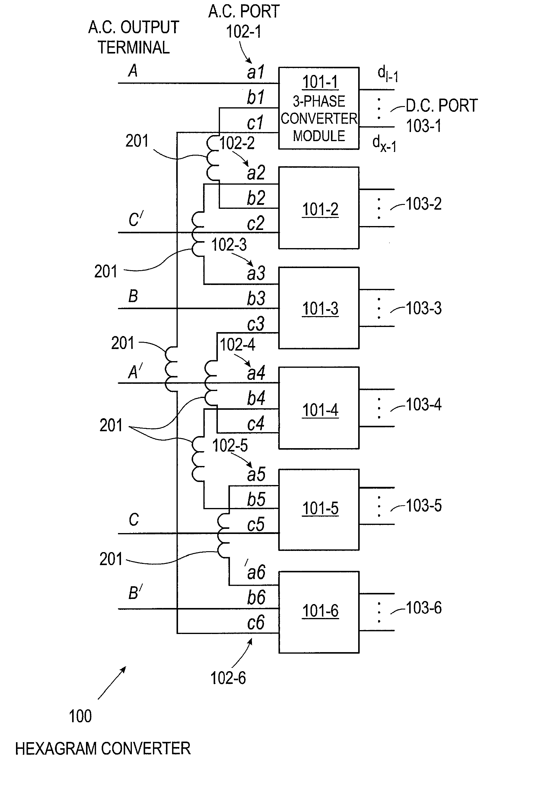
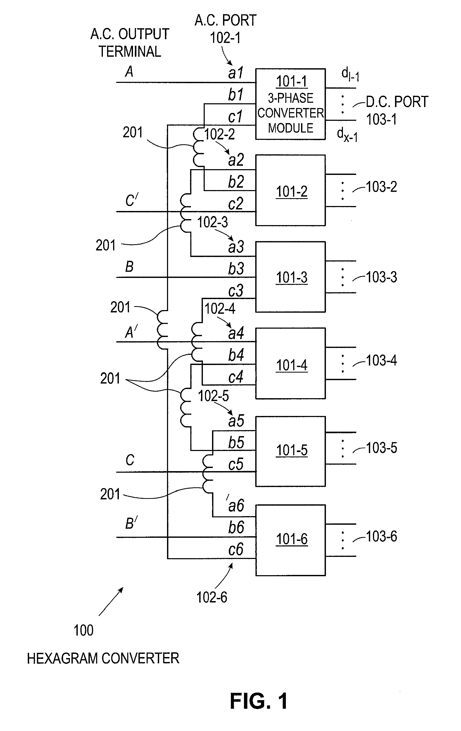
[0022]FIG. 1 is a schematic view depicting a first exemplary embodiment of multilevel converter 100, which, for ease of discussion, will be referred to herein in a non-limiting manner as hexagram converter 100. Hexagram converter 100 preferably includes six three-phase converter modules 101. Converter 100 can be configured such that each module 101 lies in a main power path and consumes one-sixth of the converter 100's output power. In some cases, when multiple versions of a similar component or structu...


PUM


Abstract

Multilevel high power converters, referred to as hexagram converters, which preferably include a combination of six three-phase converter modules, are provided herein. The three-phase converter modules are interconnected and can be configured as any three-phase converter for any given application. One or more inductors can be used in the interconnections between the six modules to suppress potential circulating currents. Numerous applications exist in which the described converters can be implemented.

Description

RELATED APPLICATION [0001] This application claims priority to U.S. Provisional Application Ser. No. 60 / 823,939, filed Aug. 30, 2006, and is fully incorporated hereby by reference.FIELD OF THE INVENTION [0002] The present invention relates to power converters and, more particularly, to converters for high power applications. BACKGROUND OF THE INVENTION [0003] Power electronics are finding increasing market space in industrial applications due to their imminent advantages in adjustable speed motor drives (ASD), unity power factor rectifications (PFC), active power filtering (APF), static var compensation (STATCOM), as well as unified power flow control (UPFC). Presently, most of their applications are in the low to medium power range from 5 kilowatts (kW) to 250 kW at the low voltage line of 208-480 volts (V), since high speed semiconductors such as insulated gate bipolar transistor (IGBT), MCT, and the like are readily available for these power and voltage levels. It is still a chal...

Claims


Application Information

Patent Timeline
Patent Type & Authority Applications(United States)
IPC IPC(8): H02J5/00
CPCH02M5/458H02M7/487H02P25/22H02M7/49
Inventor WEN, JUNSMEDLEY, KEYUE
Owner RGT UNIV OF CALIFORNIA
Why Eureka
Try Eureka