
Control apparatus for AC-AC converter

a control apparatus and converter technology, applied in the direction of electric variable regulation, process and machine control, instruments, etc., can solve the problems of loss of motors, noise or destruction of motors, and torque pulsation ascribable to low frequency components below input frequencies exerting serious influence, etc., to reduce the distortion of low frequency output voltage, enhance the effect of voltage transfer ratio, and suppress the increase of output curren

Inactive Publication Date: 2008-03-06
FUJI ELECTRIC CO LTD
View PDF4 Cites 10 Cited by
  • Summary
  • Abstract
  • Description
  • Claims
  • Application Information

AI Technical Summary

Benefits of technology

[0017] An object of the invention is to provide a control apparatus for an AC-AC direct converter that can decrease the distortion of the output voltage and the low frequency torque pulsation without weakening the magnetic flux, and can suppress the increase of an output current, even when the output voltage of the AC-AC direct converter is greater than 0.866 times the supply voltage to the AC-AC direct converter.
[0021] According to the invention, a pulsation component contained in at least one of the current components of two orthogonal axes or the absolute value of an output current vector is detected, and the phase or frequency of an output voltage is corrected on the basis of the detected signal, thereby to decrease the distortion of the low frequency output voltage when the output voltage from the direct converter exceeds 0.866 times the supply voltage. Especially in the case of driving a motor by the direct converter, a voltage greater than 0.866 times the supply voltage can be outputted without giving rise to low frequency torque pulsation, and hence, the increase of an output current can be suppressed by enhancing a voltage transfer ratio which is the ratio of the output voltage to the input voltage. As a result, there is no need to employ a motor whose capacity leaves a safety margin, and a power conversion system employing the AC-AC direct converter can be realized inexpensively.

Problems solved by technology

When a motor is connected to the matrix converter as the load of the matrix converter, the distortion of the output voltage brings about a pulsation of a torque that causes noise or destroys the motor.
In particular, the torque pulsation ascribable to a low frequency component below the input frequency exerts a serious influence.
However, the weakening of the magnetic flux increases a torque current, and the increased torque current increases the loss of the motor that causes an abnormal overheating.
Accordingly, the motor requires a larger capacity leaving a safety margin, which raises the cost of a system.

Method used


Image

  • Control apparatus for AC-AC converter
  • Control apparatus for AC-AC converter
  • Control apparatus for AC-AC converter

Examples


first embodiment

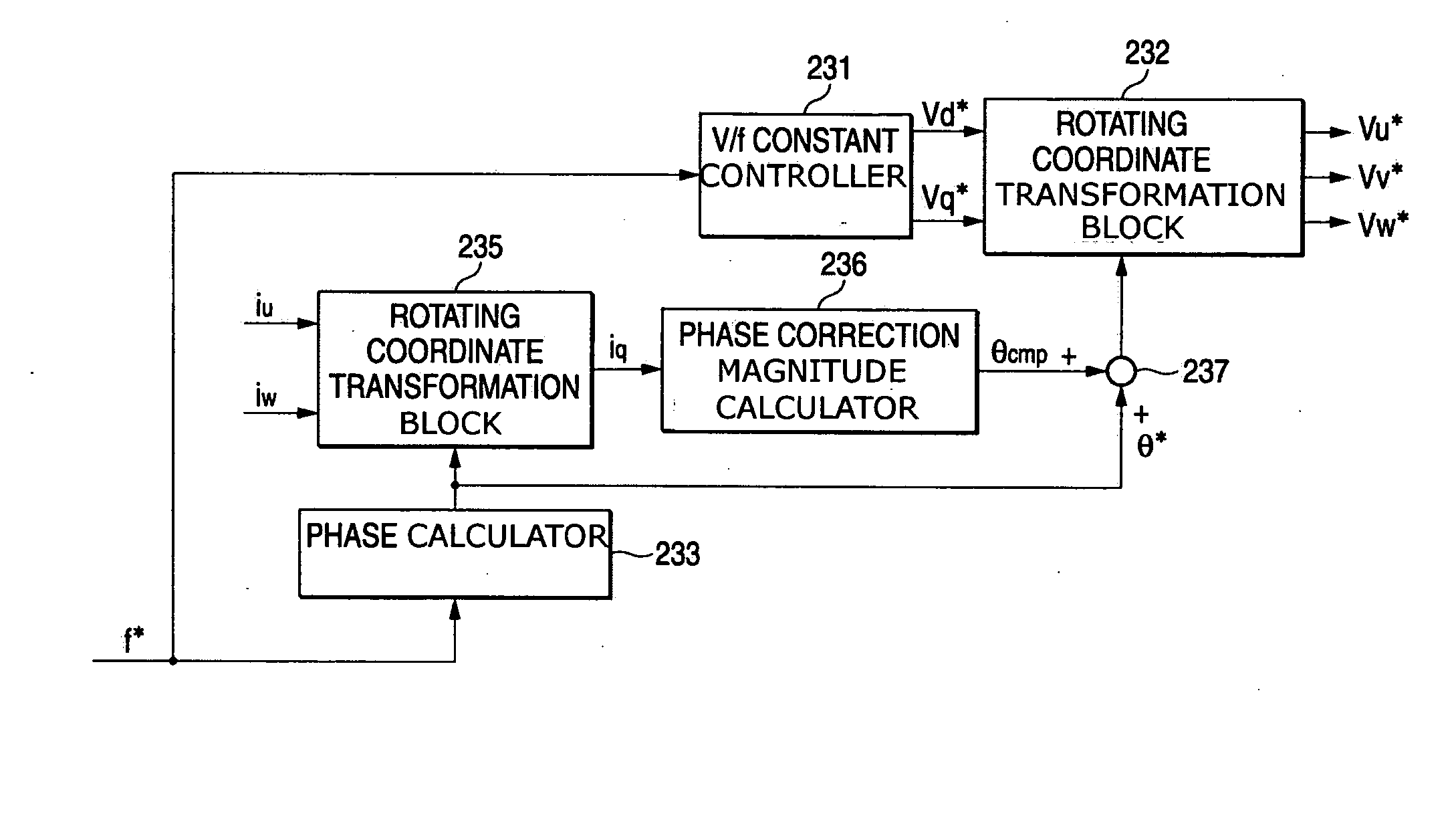
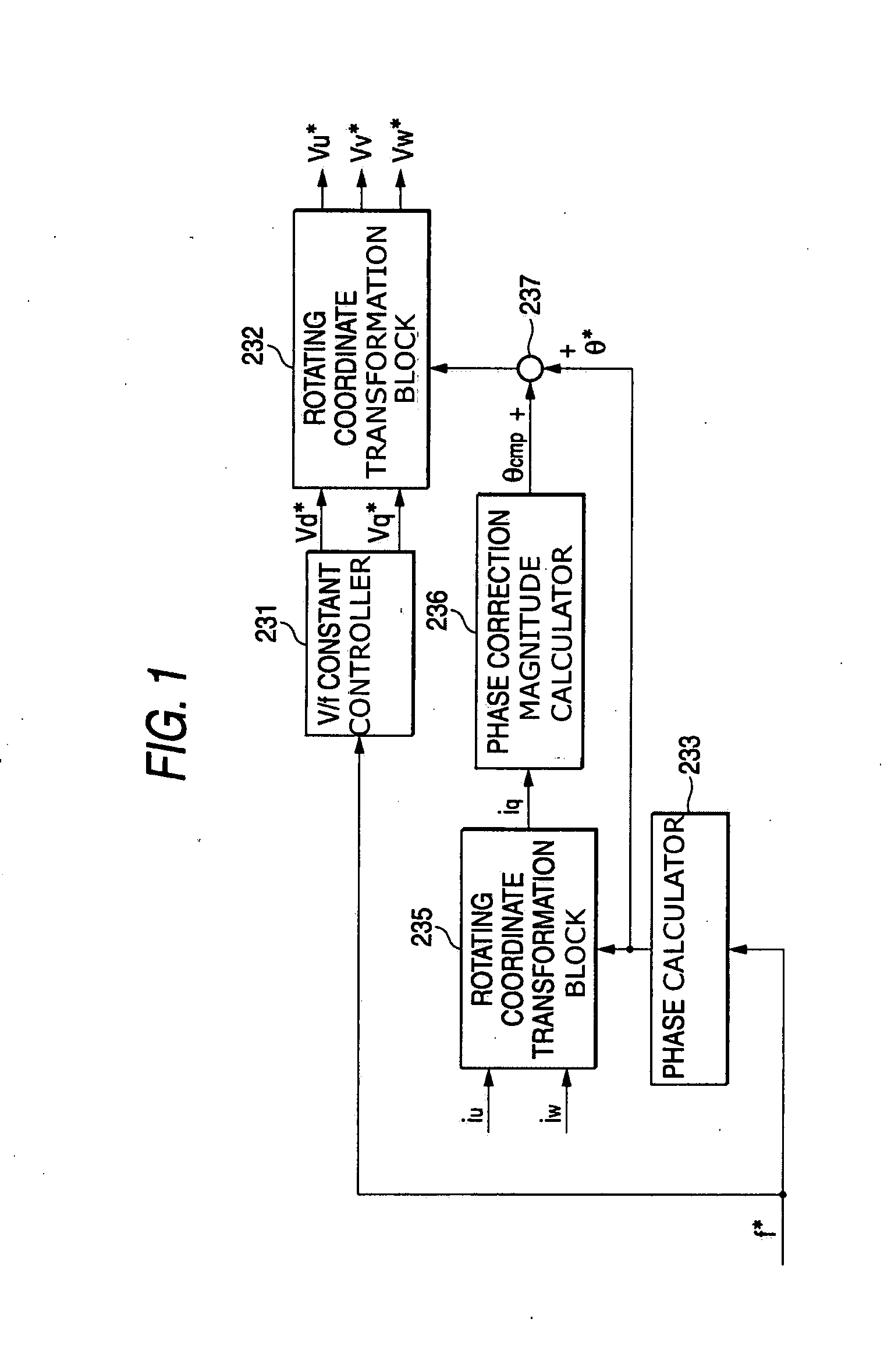
[0036]FIG. 1 shows the invention, which includes improvements in the internal configuration of the virtual inverter command calculator 23 in FIG. 9. Here, the same elements as those in FIG. 10 shall be designated by the same reference characters.

[0037] Referring to FIG. 1, a d-axis voltage command value vd* and a q-axis voltage command value vq* are calculated from a frequency command f*, as similarly shown in FIG. 10. Output phase currents iu and iw detected from a direct converter, e.g., a matrix converter, and a phase command θ* outputted from the phase calculator 233, are inputted to rotating coordinate transformation block 235 that calculates a q-axis current iq that is one of two currents components of two orthogonal axis. Also in phase correction magnitude calculator 236, a pulsation component is detected from the q-axis current iq, so as to obtain a correction magnitude θcmp for correcting the phase command θ* of an output voltage. The correction magnitude θcmp is added to t...

second embodiment

[0046]FIG. 5 is a block diagram showing the invention in which a phase correction magnitude θcmp is calculated by using the absolute value of an output current vector. Absolute value calculator 238 calculates the absolute value (=√(id2+iq2)) of the output current vector using the currents id and iq outputted from rotating coordinate transformation block 235. Phase correction magnitude calculator 236 calculates the phase correction magnitude θcmp using the absolute value.

third embodiment

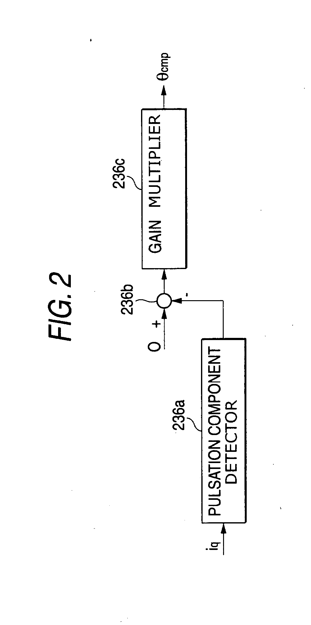
[0047] Next, FIG. 6 is a block diagram showing principal portions of the invention. The embodiment of FIG. 6 is different from that of FIG. 1 in that a frequency correction magnitude fcmp calculated from the pulsation component of a q-axis current iq by frequency correction magnitude calculator 239 is added to the frequency command f* of the output voltage by adder / subtractor 237. The frequency correction magnitude calculator 239 can be realized by the same configuration as shown in FIG. 2. The calculator 239 outputs the correction magnitude fcmp for correcting the frequency command f* on the basis of the pulsation component of the q-axis current iq. The adder / subtractor 237 provides a corrected output voltage frequency command (f*+fcmp) by adding the correction magnitude fcmp to the frequency command f*. The corrected frequency command is inputted to phase calculator 234, which obtains the final phase command θ** of the output voltage by using the corrected frequency command. Then,...


PUM


Abstract

A control apparatus for an AC-AC direct converter. The control apparatus includes a calculator providing a phase command θ* of an output voltage of the converter, a calculator providing a q-axis current iq by using output currents iu and iw and the phase command θ*, a detector detecting a pulsation component contained in the q-axis current iq, a calculator providing a phase correction magnitude θcmp so as to decrease the pulsation component, and an adder / subtractor correcting the phase command θ* by using the correction magnitude θcmp. This apparatus can decrease the output voltage distortion and low frequency torque pulsation and can suppress the increase of an output current without weakening a magnetic flux, even when the converter is operated in an overmodulation region.

Description

BACKGROUND OF THE INVENTION [0001] 1. Field of the Invention [0002] The invention relates to a control apparatus for an AC-AC direct converter in which a multiphase AC voltage is directly converted into a multiphase AC voltage of any desired amplitude and frequency by turning ON and OFF semiconductor switching elements. [0003] 2. Description of the Related Art [0004] A matrix converter has been known as an AC-AC direct converter of the type specified above. Hereinbelow, the matrix converter will be taken as an example, and the configuration and operation of a control apparatus for the matrix converter will be explained. [0005] First of all, FIG. 8 is a diagram showing the configuration of a main circuit of the matrix converter. Referring to FIG. 8, letters R, S and T denote AC input terminals that are connected to a three-phase power system or the like (also input phases of the power system shall be denoted by the same letters), and letters U, V and W denote AC output terminals to w...

Claims


Application Information

Patent Timeline
Patent Type & Authority Applications(United States)
IPC IPC(8): H02M5/293
CPCH02M5/27
Inventor TAMAI, YASUHIROYAMADA, TATSUYA
Owner FUJI ELECTRIC CO LTD
Learn More