Method of determining body orientations in space on the basis of two X-ray records

Inactive Publication Date: 2008-03-06
UNIV TUBINGEN
View PDF7 Cites 14 Cited by
  • Summary
  • Abstract
  • Description
  • Claims
  • Application Information

AI Technical Summary

Benefits of technology

[0022] One object of the present invention therefore is to provide an improved method for accurate determination of the inclination and

Problems solved by technology

The use of conventional X-ray techniques to determine these angle quantities results in two major disadvantages which make exact determination of the inclination and anteversion more difficult, or impossible.
A first disadvantage is that the angles to be determined refer to geometric lines in space, in particular to geometric structures of the pelvis.
However, the angles can be determined only inadequately from these images since the angles in space are generally imaged “in a distorted form” on flat projection surfaces.
A second disadvantage is that mathematical and technical definition of the inclination and anteversion makes sense only if these details refer to a pelvis-internal reference system, i.e. to an anatomical coordinate system.
The second of the described disadvantages is, how

Method used


Image

  • Method of determining body orientations in space on the basis of two X-ray records
  • Method of determining body orientations in space on the basis of two X-ray records
  • Method of determining body orientations in space on the basis of two X-ray records

Examples


Example

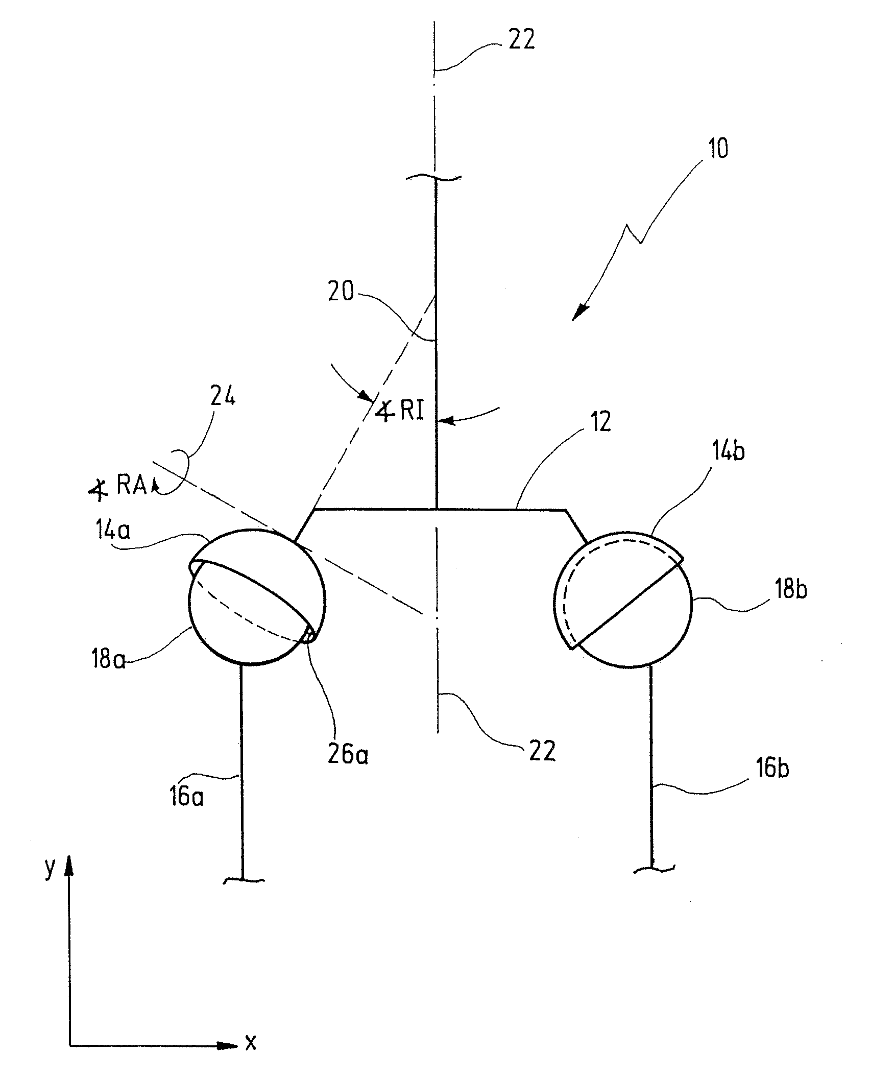
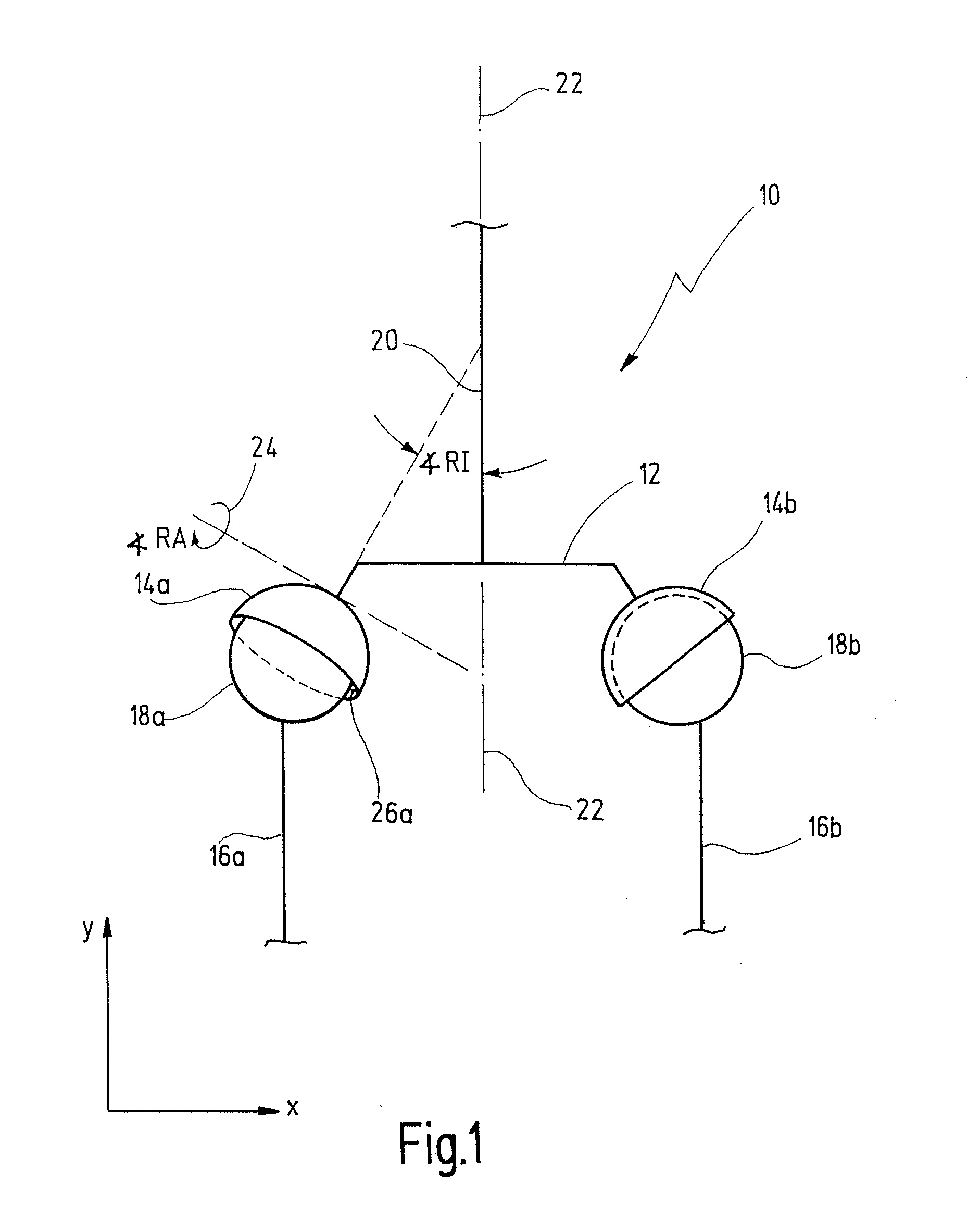
[0052] Mathematically, the orientation of an acetabulum can be represented by a normal vector {right arrow over (n)} of the acetabulum opening plane with respect to an anatomical pelvis coordinate system (see FIG. 1). The anatomical pelvis coordinate system is preferably defined with the aid of a anterior-pelvic plane, which is in turn defined by two spinae of the pelvis (“spines iliac anterior superior, SIAS”) and the symphysis of the pelvic bone. This plane is defined by the x and y unit vectors of a Cartesian coordinate system. The z unit vector of this system is perpendicular to this plane, and emerges from it. The inclination and anteversion of the acetabulum can thus be expressed in polar coordinates, in the form of the azimuth and the polar angle.

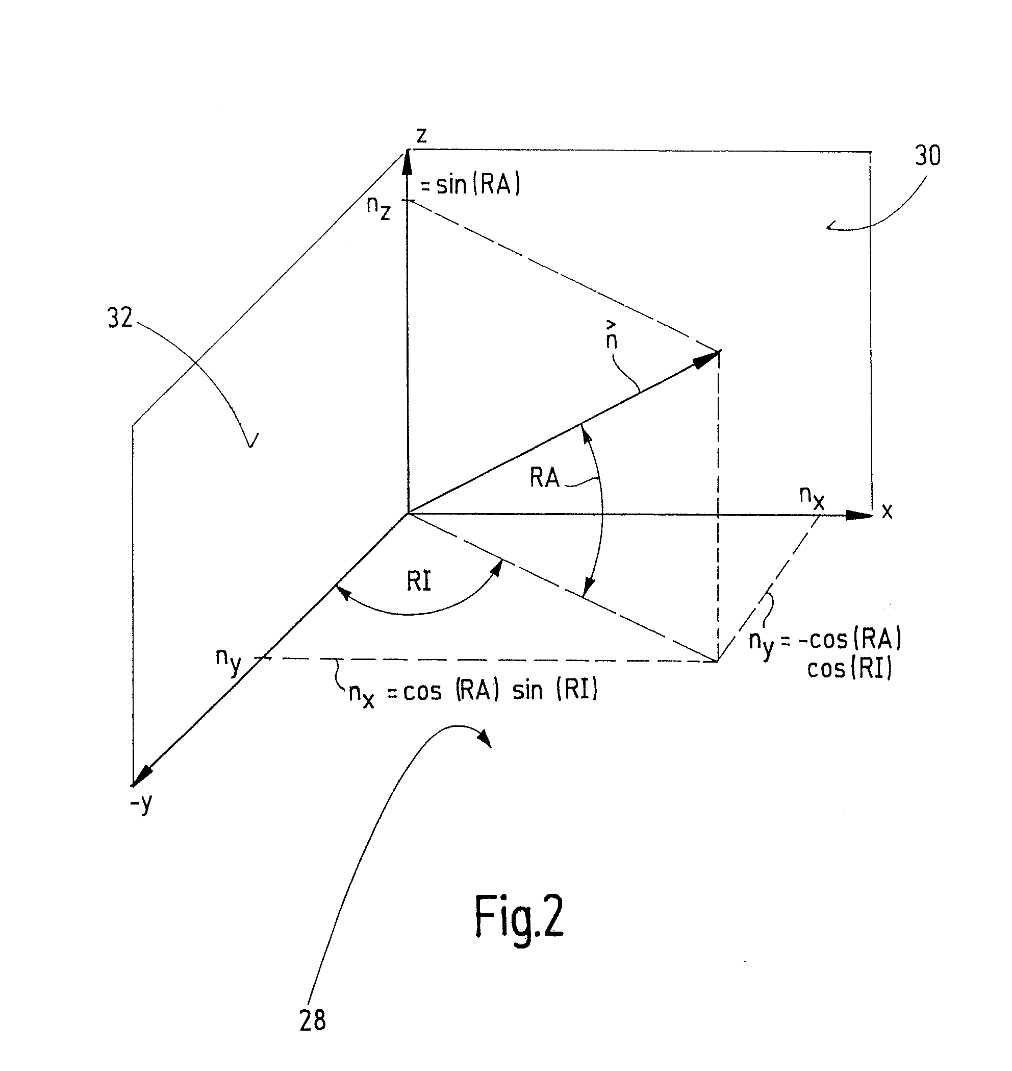
[0053]FIG. 2 shows an example of the orientation of any given vector {right arrow over (n)} in a polar coordinate system.

[0054] The normal vector {right arrow over (n)} is perpendicular to the acetabular opening surface 26 (see FIG...


PUM


Abstract

A method for determination of the inclination angle and the anteversion angle of an acetabulum of a patient in an anatomical reference system whose orientation is determined by the pelvic bone of the patient, taking account of any pelvis tilt, the method comprising the following steps: a first image of the pelvic bone is provided, wherein the first image shows a frontal plane including the pelvic bone; a first inclination angle of the acetabulum is determined using the first image; a pelvis rotation angle is determined, which indicates the rotation angle of the pelvic bone about the normal to the frontal plane relative to an optimum patient location position; a second image of the pelvic bone is provided, wherein the plane of the second image is rotated by an image rotation angle relative to the frontal plane about a common section line of the two planes, preferably about the body longitudinal axis of the patient; a second inclination angle of the acetabulum is determined using the second image; a pelvis tilt angle is determined, which represents a rotation of the frontal plane of the first image relative to an anterior-pelvic plane in the optimum patient location position; a linear equation system is set up having at least two linear equations as a function of the previously determined angles; the normal vector no is expressed in polar coordinates of the anatomical reference system; the at least two linear equations are solved for the azimuth and polar angle of the normal vector no in order to determine the inclination and the anteversion in this way.

Description

RELATED APPLICATIONS [0001] This is a continuation application of co-pending International Patent Application PCT / EP 2006 / 002287 (published as WO 2006 / 094833) which claims priority of the German Application DE 10 2005 012 708.8 filed on Mar. 11, 2005 which is fully incorporated herewith by reference.BACKGROUND OF THE INVENTION [0002] Correct orientation of the acetabulum is an important bio-mechanical precondition for long-term success of hip endoprosthesis. The spatial orientation of the acetabulum is (clinically) defined by two angle quantities, to be precise by the inclination and the anteversion. [0003]FIG. 1 illustrates a part of the human skeleton in highly schematic form, essentially showing only the area of a pelvis 10 on a so-called frontal plane and an aprior-posterior pelvis overview (a.p.-pelvis overview). [0004]FIG. 1 shows schematically, a pelvic bone 12 which has a left acetabulum 14a and a right acetabulum 14b. Acetabular bones 16a and 16b with corresponding acetabul...

Claims


Application Information

Patent Timeline
IPC IPC(8): G06K9/00
CPCA61B5/055A61B5/1071A61B6/00A61B5/4528A61B5/1075
Inventor MULLER, OTTO
Owner UNIV TUBINGEN
Why Eureka
Try Eureka