
Device and Method for Monitoring Cardiac Pacing Rate

a technology of cardiac pacing and monitoring device, which is applied in the field of cardiac pacing rate monitoring device, can solve the problems of fibrosis and heart failure, affecting the quality of life of patients, and affecting the quality of life of patients, and incorrect rate limits or rate response can have serious effects

Inactive Publication Date: 2008-03-06
SMARTIMPLANT OU
View PDF7 Cites 3 Cited by
  • Summary
  • Abstract
  • Description
  • Claims
  • Application Information

AI Technical Summary

Benefits of technology

[0017]One aspect of the invention is a device for monitoring cardiac pacing rate, wherein the device comprises a measuring unit for receiving an electrical signal representing the patient's cardiac demand, and a computing unit for determining the myocardial energy balance by calculating energy consumed by the myocardium for both a...

Problems solved by technology

The accompanying increases in wall-stress can promote hypertrophy, fibrosis and heart failure.
The artificial pacing system may drive the heart into failure while trying to meet the metabolic demand.
Incorrect rate limits or rate response can have serious impact on a patient's quality of life.
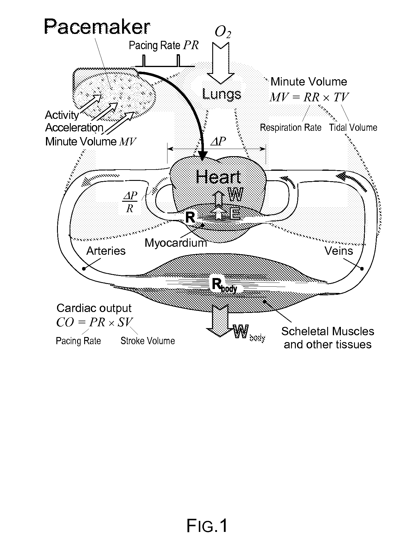
For example, postural hypotension, a sudden drop in blood pressure caused by shifts in blood volume to the lower extremities due to a decrease in hydraulic resistance, Rbody (FIG. 1), when rising from a seated or supine posture, can lead to syncope and falling of the patient, or worse.
Neurogenic syncope is a similar problem but even more insidious because the sudden drop in blood pressure may occur minutes after the precipitating event.
Myocardium damaged during an ischemic event or by other disease (e.g., diabetes) has limited cardiac reserve and capability to cope with the rising cardiac demand W.
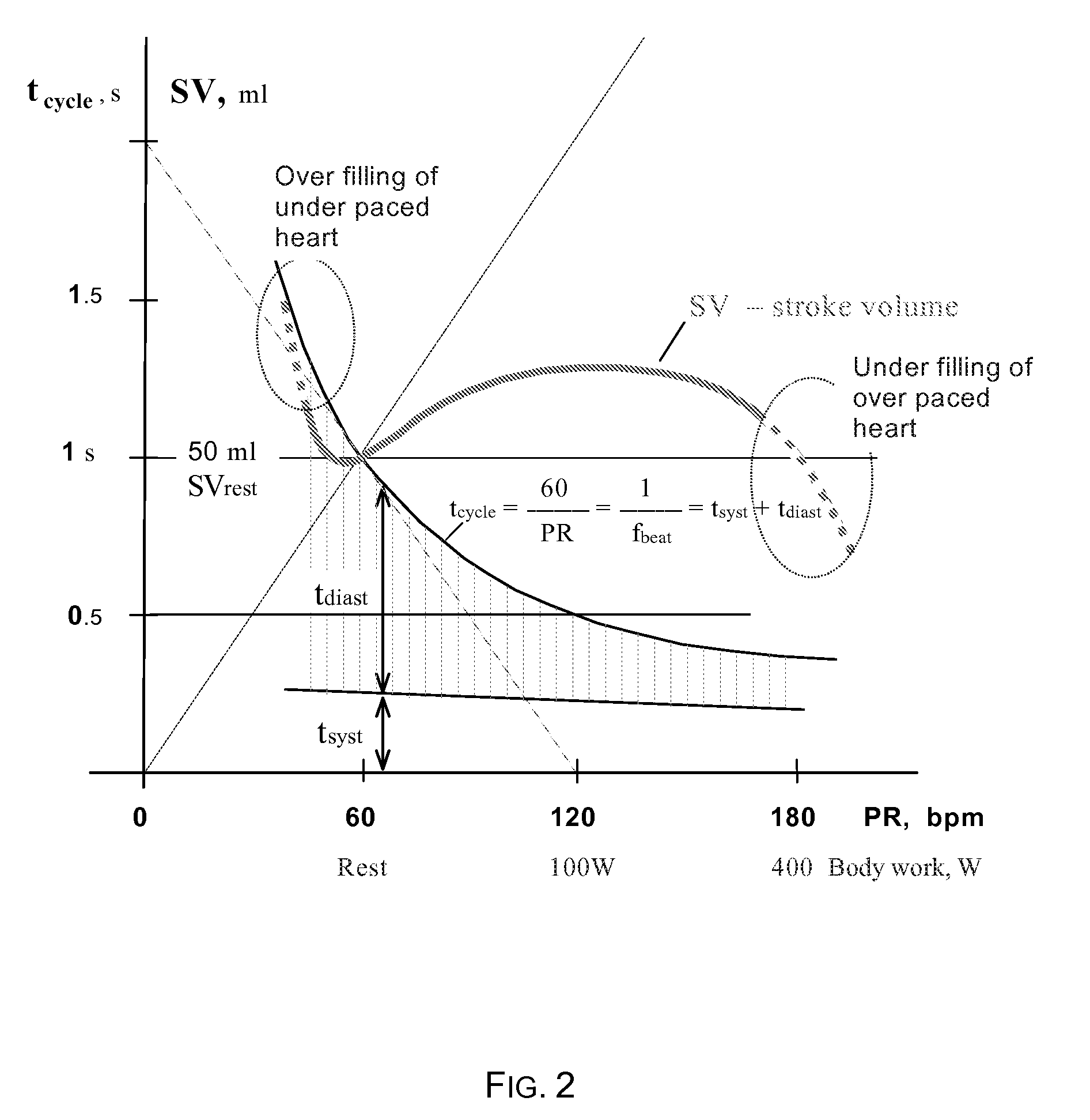
Here the limitations occur during ventricular filling.
However, constant measuring of blood pressure can be complex task.

Method used


Image

  • Device and Method for Monitoring Cardiac Pacing Rate
  • Device and Method for Monitoring Cardiac Pacing Rate
  • Device and Method for Monitoring Cardiac Pacing Rate

Examples


Embodiment Construction

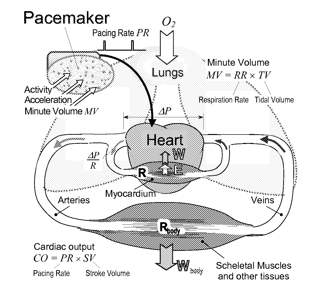
[0026]FIG. 1 depicts an implanted cardiac pacemaker with adaptive pacing rate control, and a simplified presentation of the cardiovascular system. The pacing rate must be adaptive to the patient's workload to ensure the required cardiac output CO, which is a product of stroke volume SV and heart rate HR. Several kind of body sensors monitor the level of physical work Wbody, e.g., activity and acceleration sensors, and a sensor of minute volume MV of respiration. The most adequate means for estimating the workload is measurement of variations of the electrical bioimpedance of lungs. In simple cases the pacing rate (PR) follows almost linearly the minute volume (MV) of respiration, which can be obtained directly from the measured lung impedance. However, in more complicated cases the pacing rate PR has a badly defined nonlinear dependence from the respiration rate (RR) and the tidal volume (TV). The unhealthy heart can not operate at both, significantly high and low rates because of r...


PUM


Abstract

A device for monitoring cardiac pacing rate having a measuring unit for receiving an electrical signal representing the patient's cardiac demand, and a computing unit for determining the myocardial energy balance by calculating energy consumed by the myocardium for both an external dynamic work for pumping blood into a vascular system, and an internal static work of the myocardium. Volume and time based measurements are used, and in one embodiment, volumes are estimated and volume ratios are calculated from volume estimates. In another embodiment, volumes are estimated from bioimpedance measurements. A further aspect is a rate adaptive pacemaker, wherein the maximum pacing rate is determined from the myocardial energy balance such that the energy supplied to the myocardium approximately equals the energy consumed by the myocardium for both an external dynamic work for pumping blood into a vascular system and an internal static work of the myocardium.

Description

CROSS REFERENCE TO RELATED APPLICATIONS[0001]This application claims the benefit of U.S. provisional application 60 / 823,965, filed on Aug. 30, 2006, the subject matter of which is herein incorporated by reference for all purposes.TECHNICAL FIELD[0002]The invention relates to the field of cardiovascular methods and devices for determining the pace rate from patient's myocardial energy balance, i.e. from the demand of the patient's organism and external and internal work of the myocardium. The invention can be used in various embodiments such as in rate-adaptive pacemakers. The energy balance can be determined from volume or volume ratio and time measurements, while electrical bioimpedance can be used to measure or to estimate the volume or volume ratio.BACKGROUND OF THE INVENTION[0003]There are multiple approaches for controlling a pacing rate of a rate-adaptive pacemaker to provide a heart rate adequate to meet the metabolic demand (J. G. Webster, Design of Cardiac Pacemaker. Piscat...

Claims


Application Information

Patent Timeline
IPC IPC(8): A61N1/365
CPCA61B5/029A61B5/053A61N1/36585A61N1/36521A61N1/36514A61B5/0295
Inventor KINK, ANDRESMIN, MARTPARVE, TOOMASRATSEP, INDREK
Owner SMARTIMPLANT OU
Learn More